
 |
|
 |

|
|
|
| 06-07-2018, 04:58 PM | #1 |
|
BimmerPost Supporting Vendor
3749
Rep 2,907
Posts 
Drives: 2011 E93 M3
Join Date: Nov 2014
Location: DFW, Texas
|
S65 Engine Main Bearing Service, Documented
 Featured on BIMMERPOST.com This main bearing job is not for the faint of heart and should be an engine out service. It is possible to remove the subframe and transmission to do it in car but that method will not allow the same level of precision that the engine out method allows, and removing the engine only requires about 2 more hours beyond the point needed to service the mains in car. This bearing service requires above average mechanical skill, a clean working environment, and a number of special tools. All said and done this job can can take someone upwards of 30 work hours depending on their speed of work. Due to the length of the post and above average skill level required I will be omitting detail from some of the more obvious or preliminary steps to focus more on the bearing specifics and help keep the post size reasonable. This job requires certain prerequisite tasks. This post assumes that you’ve got the engine out and mounted on a stand, as well as a good working knowledge of the S65 engine and it’s components. You need a full assortment of metric mechanics hand tools such as combination wrenches, sockets deep and shallow, impacts, internal and external torx, allen sockets, pry bars, screwdrivers, mallets, etc, plus the special tools shown below. Consider this post more a guideline than a critically written step-by-step instruction. 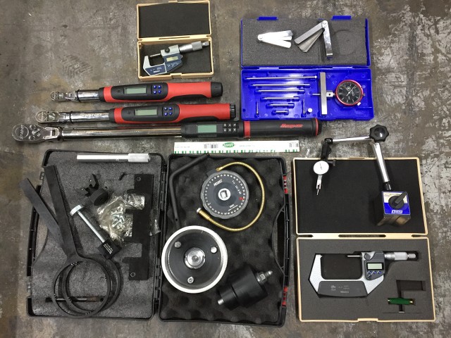 Pre-Steps: Parts purchases: We can assume certain parts will be replaced and order those ahead of time such as new BE rod bearings and bolts, certain gaskets, oils, etc, but the main bearings cannot be ordered until the engine is disassembled and measurements are taken. At that time you can order additional gaskets or parts based on your findings during disassembly. It takes about 3-4 hours to get to the “engine out” point in a shop environment depending on how you remove the engine. On a lift you can drop the subframe and drop the engine/trans out below. On jacks in a garage you can remove the front clip, unbolt the transmission, and pull the engine out from the front with a crane. For DCT cars this has the added benefit of not having to deal with the fluid fill procedure once everything is back together. Remove the flywheel as soon as the engine it out. Mount the engine on a quality engine stand. For this thread I am rebuilding an engine that had spun a rod so the entire engine had been disassembled and cleaned to remove all traces of bearing contamination (it gets into EVERYTHING). A new/used crank was also sourced, forcing us to re-measure for proper bearing shells and adding to the thorough nature of this post. For preventative services where you’re just replacing worn bearings in a running engine with no issues, it is easier as you simply need to order replacement bearing sizes (by color) identified on the block and crankshaft (explained below). That type of main bearing service would be the type more suitable for “engine in” service. 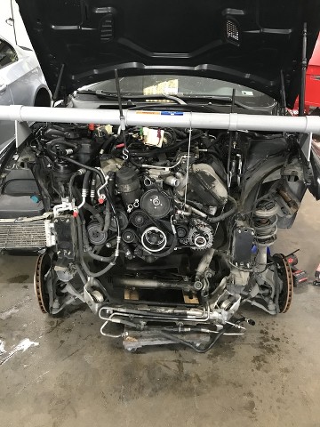 Step “1”: Remove the belts, AC compressor/PS pump, alternator, engine mount arms, etc. Everything that impedes splitting of the block or crankshaft removal must be removed and set aside. The A/C compressor can be unbolted and left in the car if you don’t have a way to properly evacuate the refrigerant. Just lash it to the frame rail and be careful not to damage it during engine removal/installation. Step 2: The timing chain tension must be removed from the crankshaft. Preliminary steps include removing the wiring, coils, valve covers, and front VANOS cover plates. Step 2A) Remove the VANOS adjusters: Bring the engine to #1TDC and install the cam blocks to the cams. First, remove the two timing tensioners (1per bank) to get some slack in the chains. Slack/Remove the VANOS bolts at each vanos; These are LEFT hand thread ONE TIME USE bolts so left to tighten right to loosen. Counter-hold the cam with a wrench while you loosen the center bolts as they are under high torque. Keep the washers and throw out the bolts. Using special tool 115370 (See pic in 18A) clamp the exhaust adjuster to remove tension from the intake gear, and insert (no need to tighten) a M5x10 holding bolt to the anti-chatter plate to hold its relative position, and then back off and remove the special tool. (This plate on the exhaust gear is spring loaded to remove gear slop between the intake gear which eliminates gear chatter). DO NOT tighten a bolt longer that 10mm into this hole as you will damage the internal rotor and ruin the adjuster. Remove the exhaust VANOS units first, then the intake adjusters and put them in a Ziploc to keep them clean. FYI they are not clocked specifically on the cam and they are the same from bank to bank. Lay the chains on the intake cam snouts for now. Note picture shows everything in the engine vee removed, this is not necessary for a typical job. 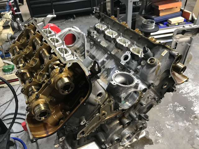 Step 2) Remove the oil pan, oil pickup tubes., and oil pumps. Store them in a big Ziploc to prevent contamination. Keep track of the small oil pump tensioner base, spring, and pin. Do not lose those. Step 3) Going back to the crankshaft, remove the pulley / vibration damper, and remove the front intermediate shaft and oil pump drive gear from the crankshaft front by removing its small center bolt. Pull off the intermediate shaft and remove the timing chains. Note, the oil pump drive gear is often stuck to the intermediate shaft and may need some force to separate so you can remove them. Step 4) Next we need to separate the bedplate. Supporting the engine while inverted becomes a critical task as the lowermost engine mount bolts are in the bedplate, which you need to remove at this point. You can use a cut to length 2x4 or whatever you think will hold the front of the engine up. The engine in my particular project was completely stripped and is being reassembled from a bare block which can be easily supported by only the two upper holding bolts. With the engine safely supported, there is a sequence (inside outwards) that must be followed when removing the many bolts from the bed plate. There are M9 Fitting bolts, removed first: 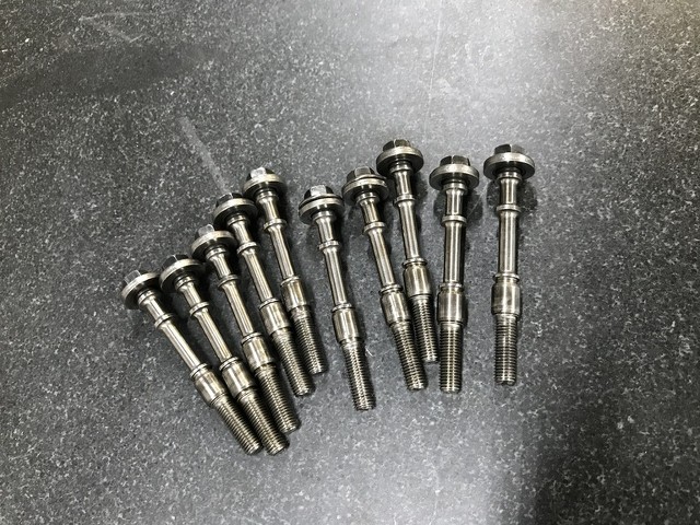 Then there are the M11 bearing saddle bolts (these hold the most bearing bore torque): 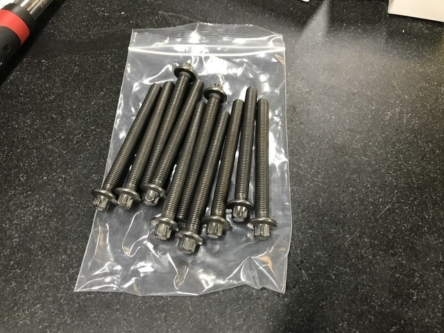 They must be removed in this order, as seen in this TIS screen capture: 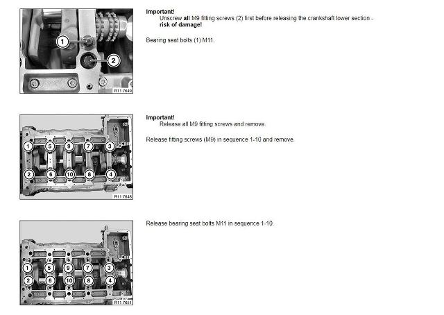 Once the center main bolts have been removed, the perimeter bolts can be removed. 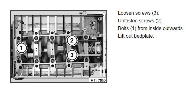 At this point the bedplate can be lifted up and removed. There will be resistance as the front and rear main seals are still installed, and the sealing agent will still be adhering to the parts at split of the block. Be careful not to move the engine around on the stand too much and disturb whatever is supporting the engine’s front. Step 5) With the bedplate removed we can next remove the connecting rods. When removing the connecting rod bolts and caps be careful not to cause damage as the split cap rods have sharp edges. Once each rod cap is removed, set it aside in a Ziploc and GENTLY push its piston/rod towards the top of the engine to gain clearance and working space around the crankshaft. Push the pistons until you feel resistance as the reach top dead center. It’s ok if they touch a valve, we are not pushing hard enough against them to cause damage. Note that each cap is already identified and matched by number to its corresponding rod to prevent mixup during reassembly. (note in pic the spun journal).  Step 6) Remove the crankshaft. It is heavy so be careful not to fumble it and nick any delicate sharp edges or journals. At this point in my particular project I continued on and stripped the entire block. Each project will have specific needs. You may wish to replace other components “while you’re in there”, or just blaze ahead with the bare minimum (yawn). My block and crank went in the washer (as did everything else). You’ll need to do some housekeeping and clean up your parts and workspace for the next steps. 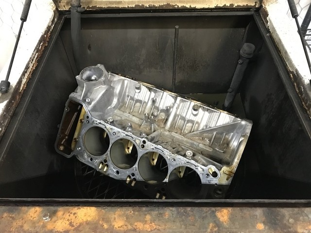 Step 7) Assess, measure, and purchase parts. There are six different main bearing combinations using BMW’s size-by-color system, there is no one-size-fits-all solution. If you’re refreshing your otherwise healthy engine, purchasing new main bearings of the same color will be quite suitable. Bearings are purchased from BMW. There are no aftermarket main bearing suppliers. To determine which bearings your engine was built with, BMW told you by engraving the block and crank with the bearing color codes. 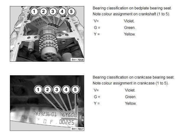 The crankshaft is laser engraved with the bearing shells to be used in the bed plate. The rear of the block is stamped with the colors of the upper shells used. Original bearing shells are labeled with their part number on the back. When the shells are manufactured they may be suitable for several thicknesses (colors) since the tolerances that differentiate them are very small. At the factory they are measured and color marked to identify their final part number. That is why the back of some of the shells have up to three different numbers. If the bearings had been previously replaced (unlikely) then they would also have an “R” connotation. See an original bearing on left, a replacement bearing on the right, (identified with an R): 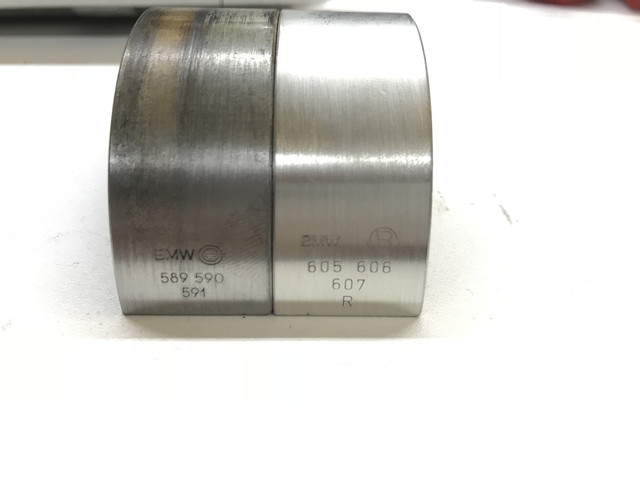 If you have a replacement crankshaft going into the engine as I do, and need to determine new sizing for the bearings, there is a way. BE bearings developed a great Wiki page around this and puts everything in one place HERE: We can measure each main journal and with those measurements determine a suitable bearing shell combination to use. This requires a high precision instrument in calibration, in my case we use a 2-3” Mitutoyo caliper with a 2" standard to ensure zero. 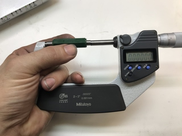 With the micrometer verified we measure each journal carefully until we get a repeatable measurement. Be careful not to nick the journals with the carbide tips of the calipers. Take note of each journal’s diameter as we will select a bearing based on our findings.  Using the handy sizing chart from BE’s wiki page we compare the crankshaft measurements to the list and determine the necessary color bearings. REALOEM LINK 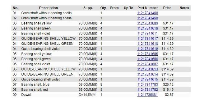 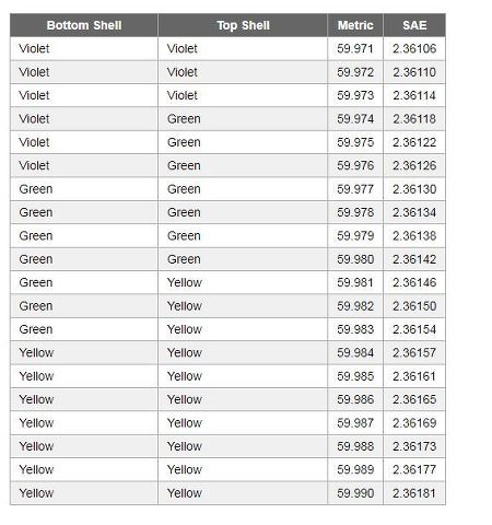 Remember to order the correct shells- there are upper shells, lower shells, and guide bearing upper and lower shells. Four different types. At this point, your project is probably going to get put on hold while you wait for parts. Dealerships don’t usually stock these bearings. They come from distribution centers and sometimes have to come from Germany so expect a little downtime. Step 7A, Optional) As an optional upgrade, you can have these bearings sent to WPC for treatment. Keep in mind this process will add about a week to your downtime. This treatment is a micro-peening process and not a coating. It actually increases the bearing clearance slightly (~.0002). I always WPC treat the mains. Here is the WPC treated bearing on the left, and the original on the right: 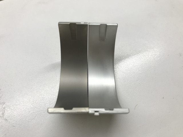 Step 8A) Now that we have the bearings and parts, we can start reassembly. Make sure you install the correct bearings in their corresponding location. Note the locator on each shell and carefully insert it into its correct orientation. Rock/rotate the shell back and forth slightly to assist in seating it. Ensure absolute cleanliness. Step 8B) It is advisable to double check the final measurements and clearances. You can do this with Plastigage or an actual bore micrometer. A bore micrometer will give you more accurate readings than Plastigage, but Plastigage has the advantage of helping identify if the main bores are out of alignment (mismatched shells) by placing Plastigage below and above the crank in each journal and taking the squish measurements after torquing. Either method requires installation of the bedplate and torquing its fasteners to ensure final main bore shape (see step 9). 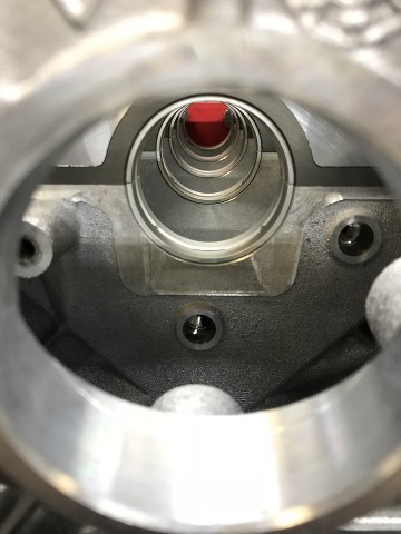 Step 8C) Setting the bore mic to the diameter of the corresponding crank journal, we use the bore mic to measure the difference in the final bore sizes to find the oil clearance. Note that you will only get accurate measurements once all of the fasteners are torqued as specified. Measurements may range from .0015-.0025. Note that unless you have a long bore mic you will need to remove the block from the stand to measure the back two journals. Also be very careful and use the mic gently on the bearings surfaces as the carbide tips of a mic can easily gouge a bearing. After measurements are taken, remove the bedplate in the same steps as in step 4 and again make sure everything is clean and ready to proceed with assembly. 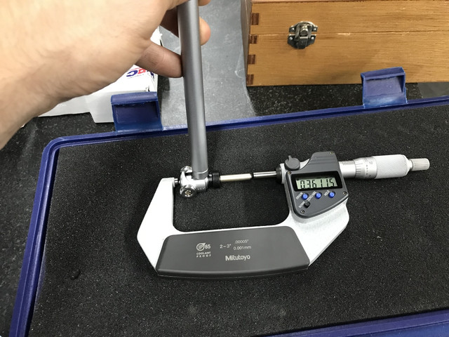 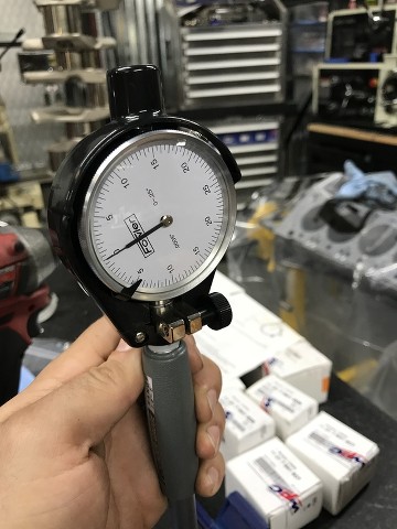 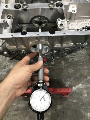 Step 9) Install crank and bedplate: With the bearing shells in their appropriate saddles, make double sure things are clean and apply assembly lube to the journals and lubricate the thrust bearing faces too. (go easy on lube on the outside rear thrust bearing as the area needs to be clean for the rear main seal). Carefully install the crankshaft squarely onto the bearings being careful not to nick or disturb them. Place some more lube on top of the crank journals and carefully and squarely rest the bed plate on the block and crank. Remember there are no locator dowels in the assembly so be careful not to tweak anything. Step 10A) This is a critical step as an error here can have an impact on the engine’s entire foundation integrity. TIS outlines this process carefully, as seen HERE. Refer to step 10B photo for the order of which you need to torque these (inward out), we start with two of the outermost 9mm “Fit Bolts” to ‘locate’ the bedplate to the block and torque them to 8nm. Once they’re in install the remaining 9mm Fit Bolts at the same 8nm. 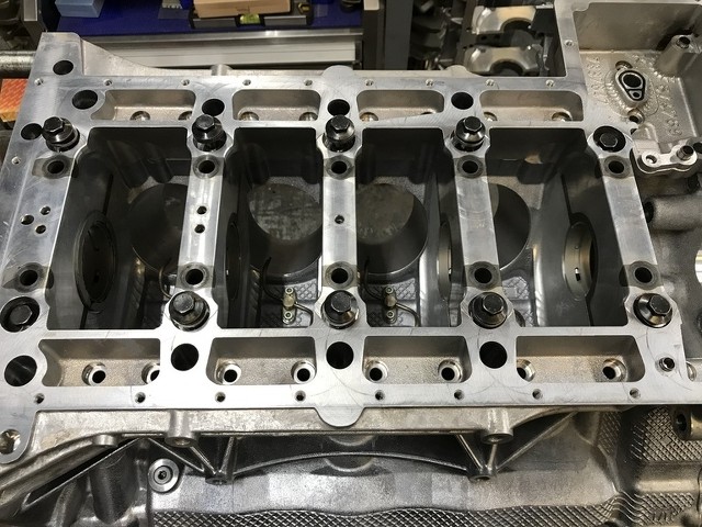 Step 10B) The M11 Bearing Bolts are the backbone to this operation and secure the most torque. Although they are stretch bolts (torque to yield aka TTY) These bolts are to be reused. If you replace these bolts with new virgin bolts the torque angles change, so pay attention in that the torque process here is for used bolts. Follow the tightening sequence shown in the picture, inward out, applying exactly 30nm to each bolt. 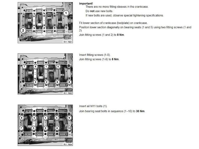 Step 10C) Mark a straight line on each M11 bolt head to identify rotation, and torque them +130 degrees using a torque angle gauge. 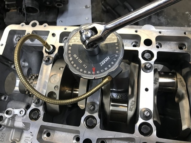 Step 10D) Torque all M9 Fitting Bolts to exactly 15nm using the same sequence as step 10b. Again, mark a straight line on the bolt head and then torque them in the same sequence +130 degrees. Step 10E) Locate all 22 of the M8x65 perimeter bolts and make sure they are clean. Install them all to 5nm first and then go back and torque them +90 degrees. The Four M8x40 bolts at the front of the block get torqued to 5nm first and then +60 degrees. The two M6x30 bolts in the front of the block get torqued to a simple 15nm. This concludes the bed plate securing sequence. At this time you should re-secure the engine stand lower bolts to the bedplate so the engine can again be safely supported. 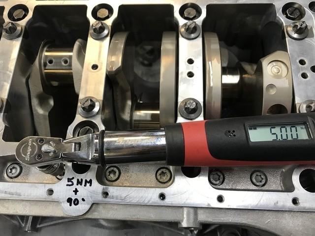 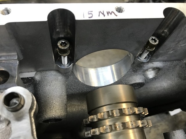 Step 11A) Insert the timing chains over the crank snout and onto their sprockets, letting them drape between the guide rails. You can also slip the other ends over the cams to keep them from falling back down later when you rotate the engine back upright. Step 11B) Install the oil drive gear onto the crankshaft first, then the intermediate shaft and secure the center bolt to 15nm. 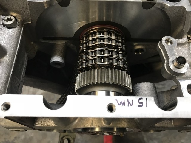 Step 12) At this point, go ahead and pull each connecting rod back up to reinstall to the crankshaft. This is when you would install the new rod bearings. (TIP) You would have more access to the upper bearing shells at step 6-7 when the crank is out. In depth rod bearing discussion is beyond the scope of this DIY and is discussed in other threads. For this thread we assume you have made your decision to replace the bearings, selected/purchased the rod bearings/bolts, and know how to install them correctly. As you pull each rod with bearing back to the crank journals to seat them, apply some lube to the bearings and install each rod cap/bearing to the corresponding rod. Remember the caps are factory numbered on the same side as the matching number of the rod, everything is identified for you so pay attention to orientations. Torque the rod bolts according to the hardware used. (BE/ARP bolts are 50ft/lb) Step 13) Now the front and rear main seals are installed. There are a few ways to do this. BMW has a very nice ($300) set of tools to install these perfectly, but I’m sure many people have (successfully?) installed them by carefully tapping them in flush with a rubber hammer, block of wood, PVC pipe section, or other shadetree method. To use the BMW tool for the rear main, the engine must be off the stand to have enough room to work. I fabricated tools in our machine shop which don’t require as much room to work and can do them on the stand. *NOTE* The seals for the S65 are very delicate with very thin wipers and no radial tension spring. Care must be taken not to nick the inside sealing edge, twist the seal during installation, or distort the outer ring during pressing it in. They are also somewhat expensive at $30-40 each if you mess up. Step 13A) Install the front seal. 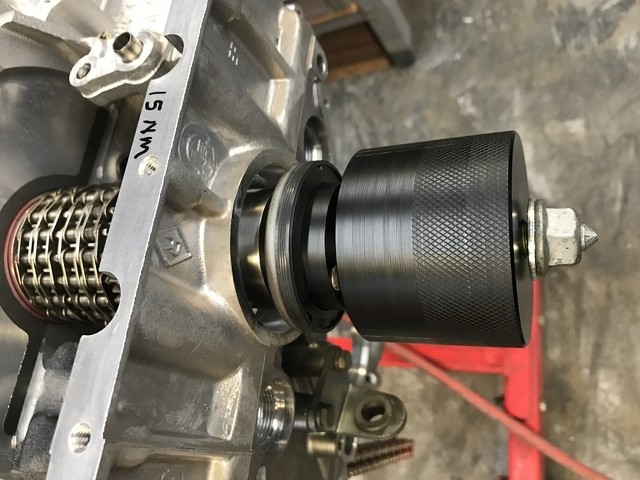 Step 13B) Install the rear seal. 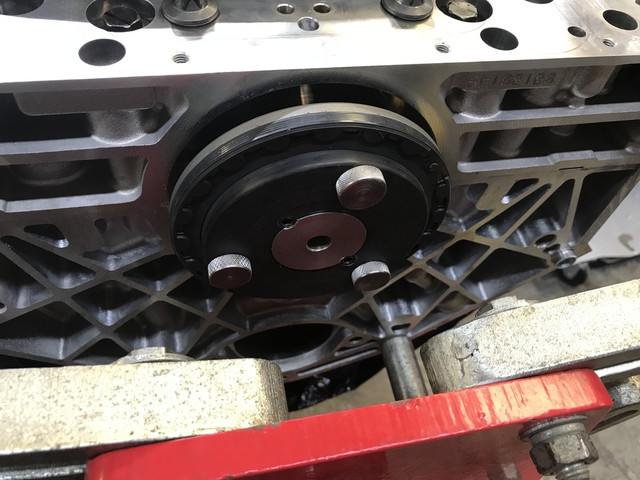 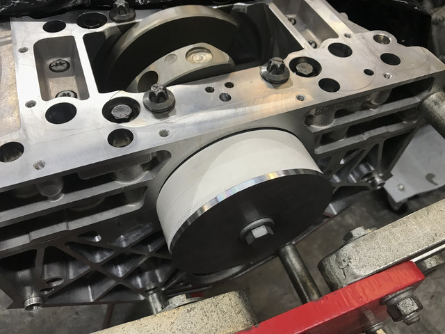 Step 14) With the crank seals installed, we need to install the “injection valves” into the block to allow injection of the split-block sealant. One on each side of the block. This can be done with the back end of a ¼” socket and a hammer, but I have a tool for it as does BMW. Carefully square it up and tap it into its bore. 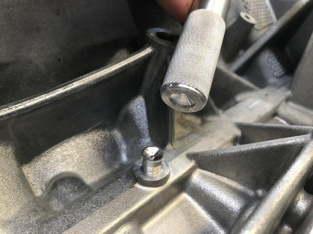 Step 15) Now the block sealant is injected. This sealant and primer has a 2 yr shelf life, so don’t order it too far in advance as the stuff you get from BMW may already be nearing expiration. You need the BMW special tool for the actual injection of the sealant. Also note that there is not much sealant supplied in the bottle, good for one engine application. When the sealant starts to ooze out at the front and rear crank seals, you need to apply the primer over the sealant which will seal and set it up. When injecting the primer hold the syringe squarely and firmly against the injection port and clean up around the site when finished. 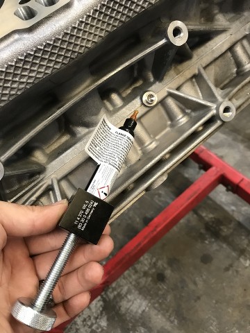 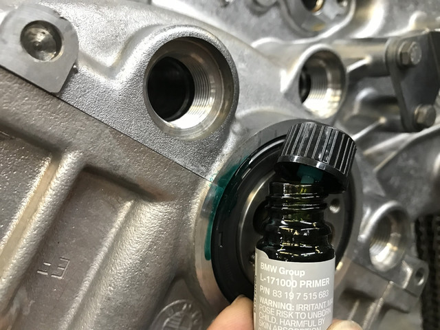 Step 16A) Reinstall oil suction pump. First install the oil pump chain tensioner pin/spring/seat, and install a new pump gasket seal. The pumps are pretty straight forward with the only potential “gotcha” being the suction pump gear lash to the crankshaft drive gear. BMW specifies acceptable lash as .06-.08mm. If you shoot for the middle of that range that is about .025”. This specification needs to be met. If the gear lash is too tight or loose you’ll end up with gear noise and/or gear and shaft wear (metal shavings). Set up an indicator as shown to measure gear slack. Set the M6x30 bolts to 5nm and tap the pump back or forth as needed to achieve your target, then final torque to 10nm and double check. 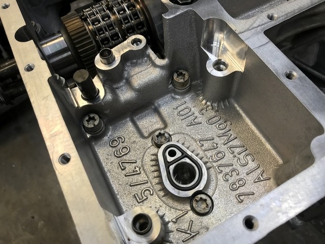  Step 16B) Reinstall the primary pump. This pump is dowel located. Tighten the bolts to 22nm. I rebuilt the pumps in the photo. If you suspect your pumps had bearing debris cycled through, you should do the same. Install new O-rings on the pickup tubes and install using blue Loctite on the 5 M6 screws going into the block (10nm). 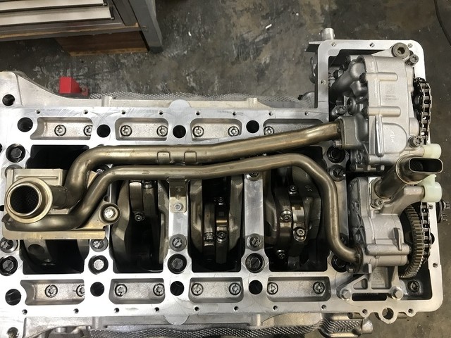 Step 16C) Install a thoroughly cleaned oil pan. Use a new gasket. You can reuse the M6 bolts, torqued to 10nm. Good time to install new drain plugs to 25nm. Make sure you clean the gasket surfaces very well with no oily residue and torque bolts working from the middle out. Also make sure before the bolts are snugged that you align the back of the oil pan flush with the trans mating surface. Install the oil condition sensor with a new seal. BONUS STEP: Now is also a good time to install a “Bimmerworld dipstick mod” if you’re into that kind of thing. You weld in a 1/2NPT bung and install the dipstick assembly into the factory pan. It’s a great way to check for acceptable oil levels without having to run the engine for a while before the oil sensor gives you any info. 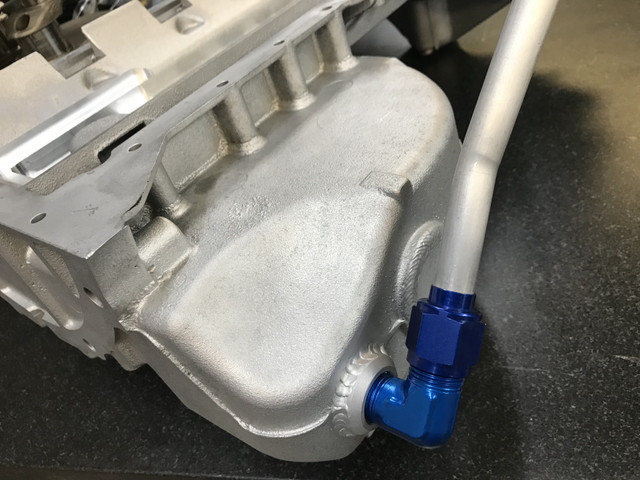 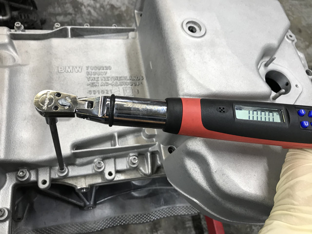 Step 17) Now, turn the engine right side up as we need to Reinstall the vibration damper. Per BMW there are a number of special tools for this task to hold the flywheel and damper, but you can do without them as long as you can secure the crank from rotating while you torque the four holding bolts to 60nm+40*+40*. If you’re equipped to check it, this is a good time to increase your cam timing accuracy by checking the piston’s true TDC position in relation to the damper. (The damper dowel pin is loose enough to allow for a crankshaft degree or two of inaccuracy). When you perform this step you can achieve a perfect TDC in relation to the damper. This is important as the holding tool used in the next step uses the TDC notch in the damper.  Step 18A) Reinstall the four VANOS adjusters. Next set the timing. This can be a voluminous DIY in itself, so please see the TIS document for adjusting if you need critical direction. I’m covering this more as a casual overview. First on bank 1 at #1 TDC install the cam locking fixtures. The cams need to be right side up having the ID engraving facing up. Using new center bolts in each adjuster, and new O-ring on the back of each adjuster (PN 11367839292), slide the chains onto the intake adjusters first and carefully reinstall them onto the cams (there is no required orientation here). Install the exhaust adjusters: Apply BMW special tool to take up the anti-chatter plate, Take note to install the exhaust adjusters with the holding screw and BMW tool facing upwards so you can access it once on the cam. Finger tighten all center bolts so you can still rotate the adjusters on the cams. Once installed you can remove the holding screws on the exhaust adjuster, and then the special tool. Finally, reinstall the chain tensioner into each bank. 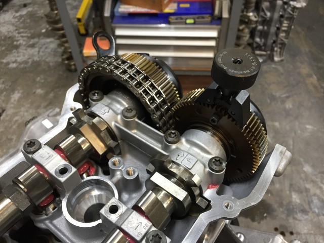 Step 18B) With the new center bolts in the four adjusters and the cam locking tools in place on the bank 1 cams, rotate the engine counterclockwise to the -10 TDC mark and then torque the intake center bolt to 20nm, then 80nm + 200* to stretch it, then release it and repeat for the exhaust bolt. When done, snug these bolts back to 10nm and move the engine clockwise to TDC. This step drags and tightens the chains to remove any slack from them for the final step which actually sets the timing. Step 18C) Set the timing by tightening the Intake bolt to 80nm + 200*, then again for the exhaust bolt. Remove the holding fixtures. Repeat 18B and 18C for bank 2. 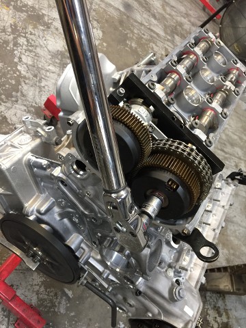 Step 19) Check the timing. It is important to not skip this step. Manually rotate the engine clockwise two times (one cycle) to settle the chains and then perform the checking procedure according to TIS. Step 19A) You must check bank 2 first, with the engraved cam ID’s facing upward. Each timing block must fit over the cam ledges squarely and both sides of the fixtures should sit flush on the head. There is a 1mm allowance per BMW here, but try to time it as close to zero as you can. 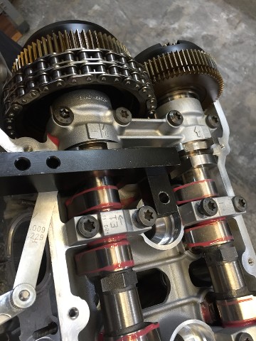 STEP 19B) After confirming bank 2 is correct, bank one must be at overlap position (cam ID facing downward). Rotate the crank clockwise ONE rotation to TDC location, inserting the lock into the damper. Same as step 19A, your timing blocks should sit flush on the head surface. Make any adjustments as needed and remove all tools. STEP 20) Replace all valve cover components and top end. There is one tip for reinstalling valve covers and their gaskets to prevent them from leaking soon after. The gasket grooves in the covers flake and the magnesium corrodes leaving a rough surface for the gasket to seal against. You can use a rotary tool and small wire wheel to clean the grooves which will stay sealed longer than if you don’t do this.  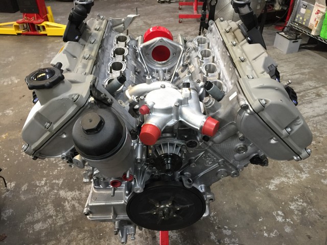 That’s the engine-out main bearing job. The rest from here is simple reassembly which doesn’t need to be documented here. “Reassembly is the reverse of removal”. It’s advisable to install new engine mounts, belts, and anything else that appears worn or you want to do preventatively, such as a new oil filter housing gasket, water pump/thermostat, etc. I use 10w60 here which is a great oil for my clearances and Texas heat. If you’re in a colder climate you may experiment with alternative weights. There is no “need” to waste good oil and do an oil change soon after this job but changing and inspecting the oil filter would be good after a few hundred miles. Finally, If you used plenty of assembly lube, there really is no need to crank/no start the engine for “pre-lube”. Just start as normal and it will build full oil pressure in only a couple of seconds. There is no break in for bearings, bit it is wise to let the engine get up to temperature easily and driving carefully, using your senses to observe anything out of the ordinary that may spell trouble- before going crazy. Bearings removed: 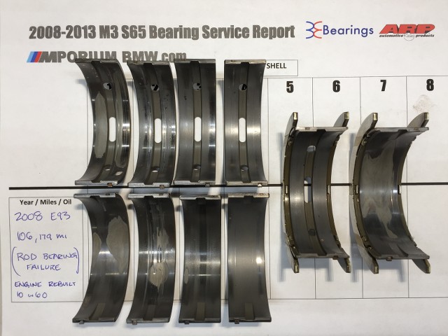 Rod bearings, (Spun second journal at 106k) 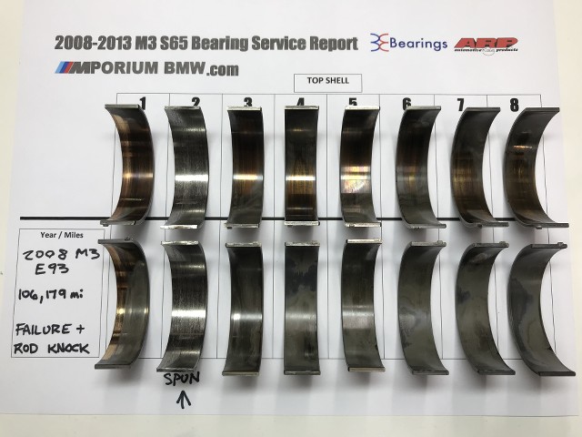 Cheers  Last edited by deansbimmer; 06-08-2018 at 09:27 AM.. |
|
Appreciate
68
8500RPM152.00 Audioslave686165.00 EnVe461037.50 MPower790.00 Mvy540.50 Scharbag2620.50 ///MPower15501.00 BayE301341.00 XKxRome0ox1587.50 330ciprem228.50 exVtekGuy115.00 aswy6261.00 Shredicus529.00 schnell1982345.00 msan402.50 Todd0131379.50 Aktavate245.50 Jobe.99.00 K-M390.50 jmeek8337.00 jdamore432.50 Nonecure77.00 Elite4722.00 Timujin351.50 L4ces337.00 Teufel_Hunden8355.00 PACarGuy679.00 admranger2984.50 CSBM52721.00 M3an V825.50 S65B40YYC34.50 Jason40748.50 FLOSS M385.50 imperfectluck425.00 FMLYSDN1181.50 Anthony3DHeli142.00 vincE92M3564.00 javmilenko699.00 |
| 06-07-2018, 05:14 PM | #2 |
|
Major
 529
Rep 1,122
Posts |
Holy smokes! Thanks for doing this. It certainly makes the rod bearing procedure look like an oil change in comparison.
 |
|
Appreciate
1
DIXIE NORMUS16.50 |
| 06-07-2018, 05:39 PM | #3 |
|
First Lieutenant
 152
Rep 303
Posts |
Very nice writeup sir. Any chance we can see what the original mains looked like and how many miles were on them?
|
|
Appreciate
2
deansbimmer3748.50 Robocop30512.00 |
| 06-07-2018, 05:51 PM | #5 |
|
Captain

541
Rep 979
Posts |
Thank you for doing this. I really appreciate the time it took.
__________________
Harrop Supercharger, BPM Tune, K/W Coil over kit, Stoptek BBK, Magnaflow exhaust, ear to ear grin everytime I drive... |
|
Appreciate
0
|
| 06-07-2018, 06:08 PM | #6 |
|
Lieutenant Colonel

1341
Rep 1,881
Posts |
Very cool, now i know that i will not be tackling this job myself anytime soon! this does make the RB replacement seem extremely simple. 30hours is a reasonably amount of labor time, and parts cost is probably not too crazy. Im tempted to drive my car down to you and visit friends in TX. would be nice to have WPC treated main bearings along with BE RB. would provide much peace of mind when i am pushing the car extra hard. i can fly back in a month when the car is ready and enjoy a peaceful road trip home!
|
|
Appreciate
1
deansbimmer3748.50 |
| 06-07-2018, 06:38 PM | #7 |
|
Major
352
Rep 1,005
Posts
Drives: GMC Sierra
Join Date: Jul 2012
Location: California
|
Forum member of the year.
|
|
Appreciate
11
Scharbag2620.50 Bartledoo2691.50 jmeek8337.00 admranger2984.50 S65B40YYC34.50 imperfectluck425.00 8_is_enough197.00 J-blackbond0.00 deansbimmer3748.50 tigermack473.50 Robocop30512.00 |
| 06-07-2018, 07:53 PM | #8 | |
|
Private

37
Rep 50
Posts |
Quote:
|
|
|
Appreciate
1
Robocop30512.00 |
| 06-07-2018, 09:22 PM | #9 |
|
Lieutenant General
 5225
Rep 10,610
Posts |
That is awesome, deansbimmer! I will be doing this in the next year or two. I did my rod bearings in 2014 and was planning to do them again and would like to do the mains as well at that time and then probably supercharge the motor.
|
|
Appreciate
2
deansbimmer3748.50 L4ces337.00 |
| 06-07-2018, 09:22 PM | #10 |
|
Brigadier General

1421
Rep 3,001
Posts |
Thank you for documenting this deansbimmer!
__________________
INSTAGRAM: GORDON.M3
North American Mr12Volt Carplay/Android Auto Distributor DINAN | EVOSPORT | VAC | ARP | RD SPORT | NEEZ | EIBACH | CSF | IND | BILSTEIN | KLASSEN | BREMBO | ENDLESS | BBS | BPM SPORT | PROJECT MU | EVENTURI |
|
Appreciate
1
deansbimmer3748.50 |
| 06-07-2018, 10:08 PM | #11 |
|
Colonel
 
2621
Rep 2,138
Posts
Drives: 2011 E92 M3
Join Date: Oct 2017
Location: Victoria
|
__________________
 2011 E92 M3 - 6MT, ZCP, ZF LSD, ESS G1, Some other goodies... |
|
Appreciate
0
|
| 06-07-2018, 11:13 PM | #13 | |
|
Colonel
2621
Rep 2,138
Posts
Drives: 2011 E92 M3
Join Date: Oct 2017
Location: Victoria
|
Quote:
Thanks for the information on this. The process resonates with my OCD!! Cheers,
__________________
2011 E92 M3 - 6MT, ZCP, ZF LSD, ESS G1, Some other goodies... |
|
|
Appreciate
1
deansbimmer3748.50 |
| 06-07-2018, 11:59 PM | #16 |
|
Private
25
Rep 69
Posts |
Gees if this is just "above average mechanical skill" then I'm definitely below average then.
This thread pretty much is a "don't try this at home folks" ad for these professional workshops. |
|
Appreciate
0
|
| 06-08-2018, 11:12 AM | #18 |
|
Brigadier General
720
Rep 3,964
Posts |
 For you Dean!!
__________________
2020 Ford Mustang GT 6MT PP1 444rwhp
(Sold)2013 M3 Coupe-MR/BLK ZCP, 2011 M3 Coupe-MR/Blk 2007 Porsche 997C2S Speed Yellow/Blk sport seats 2004 BMW M3 Imola/Blk |
|
Appreciate
0
|
| 06-08-2018, 03:30 PM | #19 |
|
Lieutenant
378
Rep 413
Posts |
Nice write up. One thing I do slightly differently that makes splitting the bedplate from the block far easier is to use the fit bolts as jacking bolts. Release the fit bolts per guidance, but only until CCW rotation increases in resistance as it tries to pull the doweled portion out of the bedplate. Now, release all of the main bolts in sequence until they spin free, but leave them in their holes.
Then, working from one end to the other, 1/2 turn at a time, continue removing each fit bolt. The combined resistance of each fit bolt will then lift and separate the bedplate from the block without any prying or fuss at all. Once you have about 1/8" separation on the block and bedplate, spin main bolts back down until the heads contact the bedplate to prevent it from rising anymore. Now, fully remove all the fit bolts, then all the main bolts. Done, no muss, no fuss, no chance of gouging the interface area prying, or any other damage. Careful with the fit bolts as well and cleaners. Even mild alkaline detergents at 50C in my ultrasonic will cause the coating (black oxide?) to flake off. Utmost care is required tightening these fit bolts on reassembly. Break one and you're in for a fun time extracting it. Edit: Also, you can make quick work of cleaning the sealant channel on the bottom of the block using a heat gun and small blade flat head screwdriver. I've gotten it down to about 5 minutes now. |
|
Appreciate
5
|
| 06-09-2018, 06:28 AM | #20 | |
|
Major
352
Rep 1,005
Posts
Drives: GMC Sierra
Join Date: Jul 2012
Location: California
|
Quote:
__________________
We grow food to feed the animals so we can eat the animals
 |
|
|
Appreciate
0
|
| 06-09-2018, 07:09 AM | #21 |
|
Banned
8355
Rep 2,963
Posts |
Hell of a write up deansbimmer! Appreciate your contribution to the forums.
|
|
Appreciate
1
deansbimmer3748.50 |
| 06-09-2018, 09:48 AM | #22 |
|
Retired Curmudgeon
2985
Rep 4,047
Posts |
Most outstanding! Easy decision not to do this myself!
__________________
 '19 X3 M40 Carbon Black/Oyster, '23 Jeep Grand Cherokee L Summit, Past BMWs: '18 M550i, '18 330 GT, '16 X5 40e, '11 E90M3, '06 X5 4.4, '03 330i ZHP, '02 M3, '97 Z3 2.8, '95 M3 (2x), '94 530i (manual), '92 525i (manual), '88 M3, '87 325iS |
|
Appreciate
0
|
Post Reply |
| Bookmarks |
|
|