
 |
|
 |

|
|
|
| 07-06-2009, 07:38 PM | #1 |
|
135
Rep 1,825
Posts |
DIY Elite Angels
THOSE WITH PRE-MARCH 2007 CONTACT ME FIRST!!!
Total install on the plug and plays is about 15-20 min. Very easy with simple tools. Tools alll you need is 1. 10mm socket 2. 13mm socket 3. zip ties (provided) scissors to cut the excess 4. flat head screw driver Before you even start as a note. The circuit it self is kinda fragile just be careful not to drop it or break any of the components. 1. First off disconnect your battery in the trunk. (if you dont know how to do this there is a few DIY on it) 2. Next remove the plastic cover that is over the positive post shown here here is where it is located in the engine bay 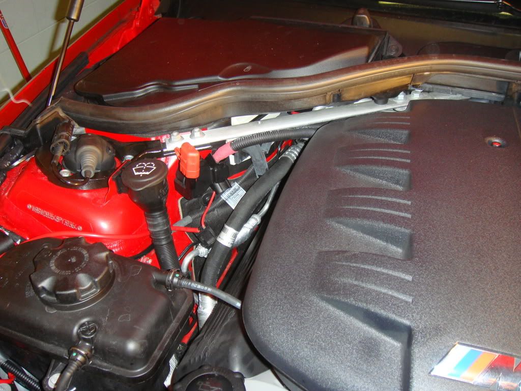 Here is the cover up close 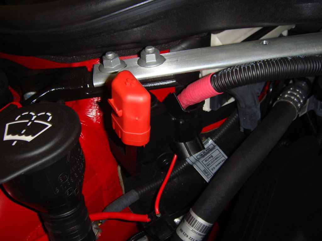 should look like this after removed 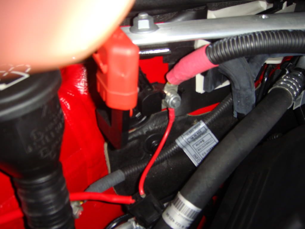 3. Next unscrew the bolt shown in the pic above with a 13mm socket 4. Take the thick red wire that looks like the one shown bellow with the ring terminal on it from the harness and attach it to the threaded shaft and bolt down the connection like shown above. Make sure it is pointing down so the plastic cover goes back on 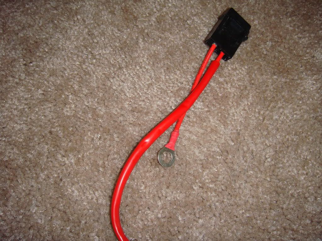 5. As for the ground. You will see a few grounds behind the windshield fill neck. Put the ground wire on one of these ground posts 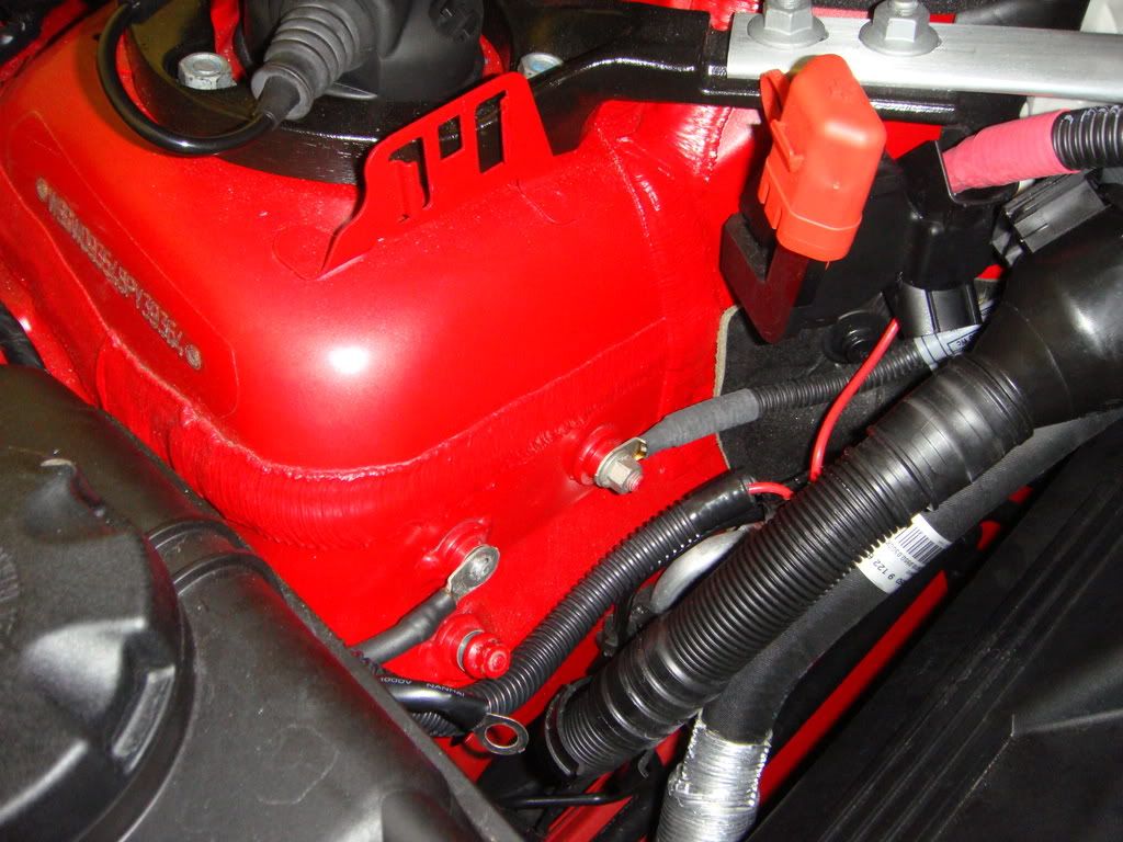 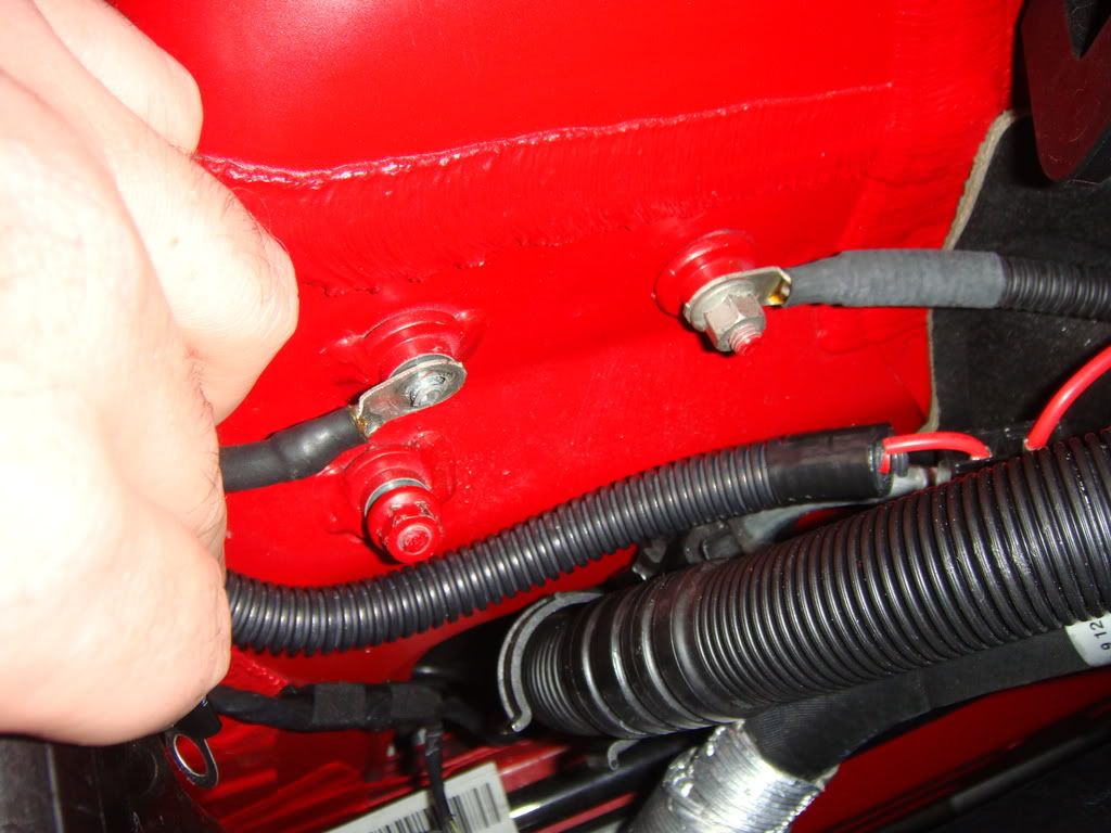 6. Run the wire in the wire behind the winshield washer tank neck and route it as shown. I put some wire loom to make it look cleaner. After running the wire this is how it should look 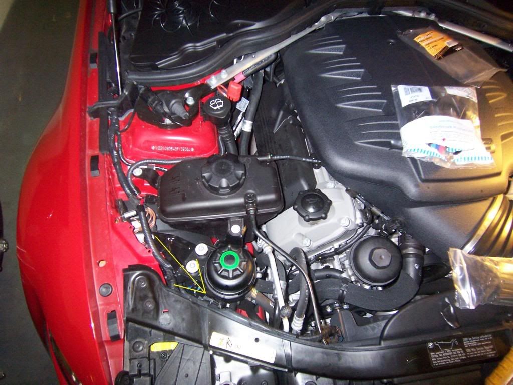 7. Next open the lid that contains your halo's bulb. Lift the tab as shown. 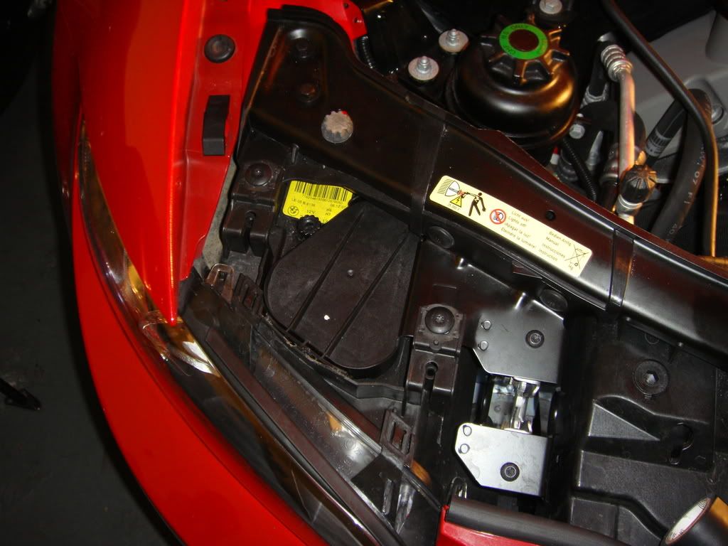 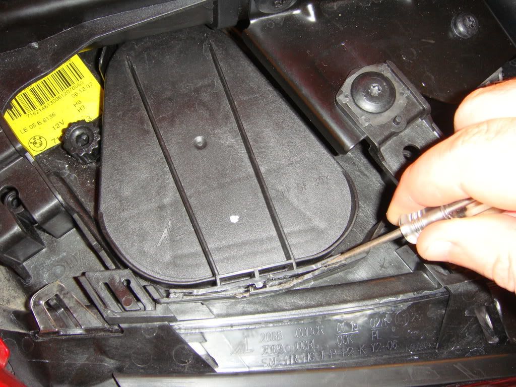 8. Next located the stock bulb you can see it here in the headlight are after the lid is removed 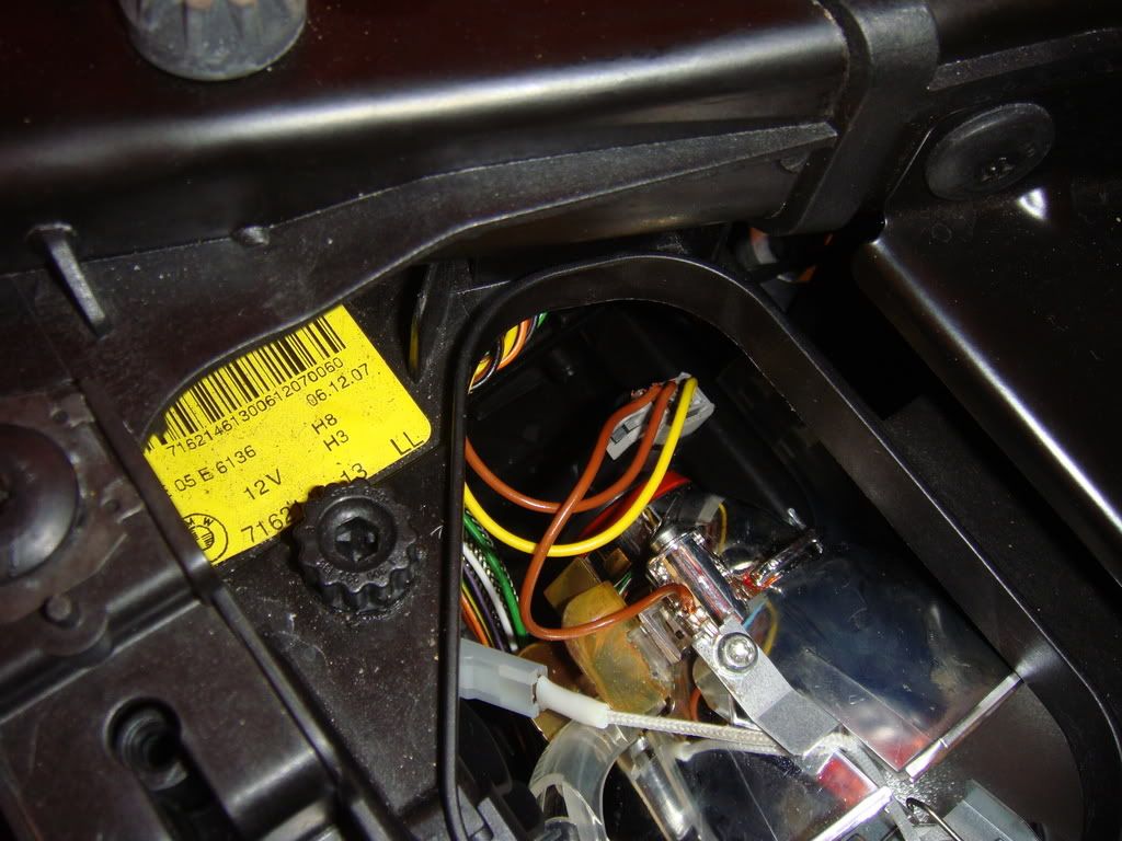 Twist it counter clockwise and pull it out like so. 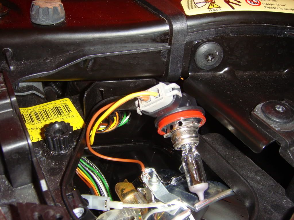 Disconnect the factory wiring harness from it Next put in the new GP bulb on to the wiring harness (only goes one way) Its going to take some twisting and turning around to get the bulb with the wiring harness on it to fit but trust me it fits. Make sure you leave the plugs from the harness outside of the cannister so the lid can go back on. Run the wires comming from the circuit in the same fashion. I notched my lid in the back as shown to be able to run the wires out. You dont have to notched your lid though. I repeat its not required to notch your lid the wires will fit running out the back witout notching it will just pinch the wires slightly but its ok. Just make sure if you do want to notch your lid you dont cut the actual rubber seal 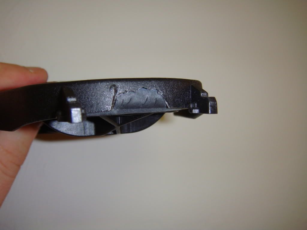 This is how i placed the wires toward the back of the lid so you dont see the wires 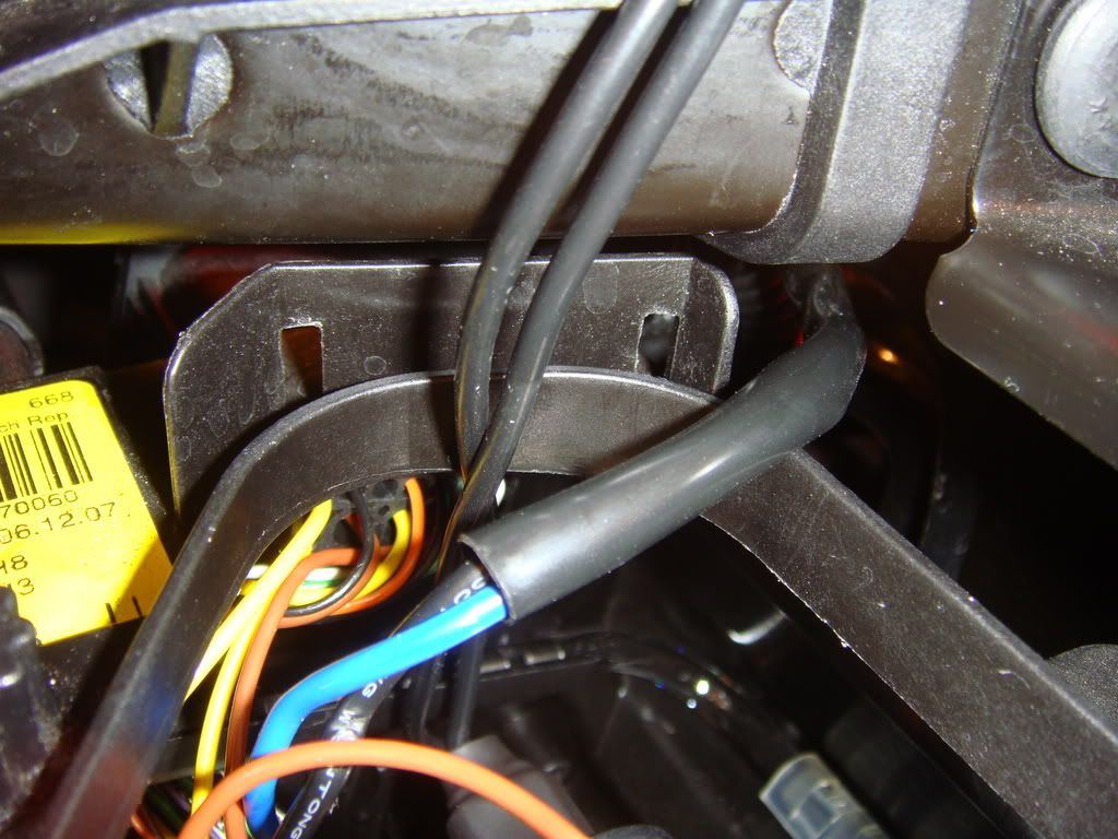 9. Connect the circuit with the plug and play connectors. The yellow wire on my white plug and play plug hould be connected to the yellow wire on the factory plug like this. Dont mind the picture its just the plug in the picture is black and the one you have is white. Just makes sure yellow goes to yellow and the blue wire on MY plug goes to the brown ones on the car. 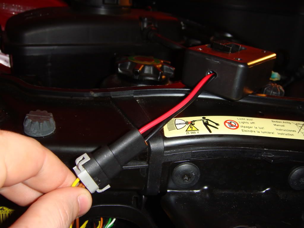 PLEASE NOTE: some of you depending on your build date ( i believe there is only two or so. I marked your kit deferently with making tape tags. Please if your kit is marked obey those tags. Only a very few should be this way (pre march 2007 builds) 10. Then connect the connectors coming out of the circuit. One will be red and the other black. They will both be female. Connect the black to the black and the other two connectors togethger 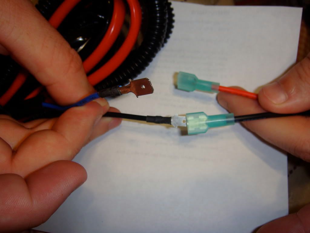  11. Then run the other longer of the plug and play plugs that plugs into your bulb of choice shown in between the top of the fan shroud and under the cover. 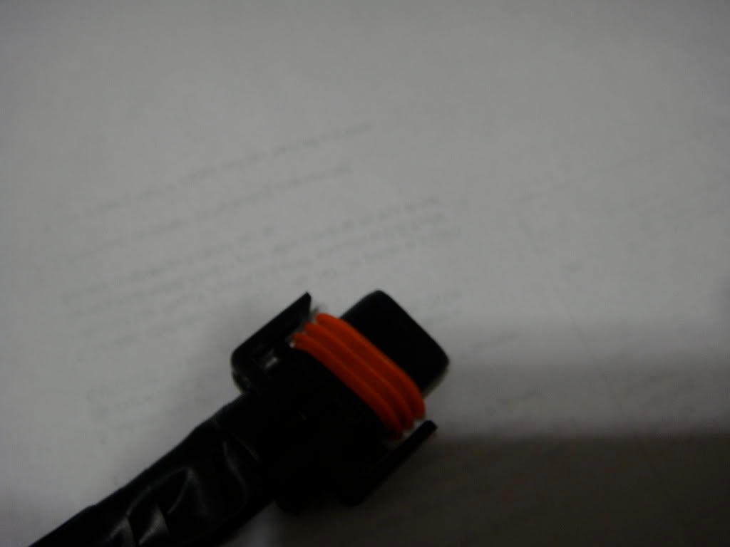 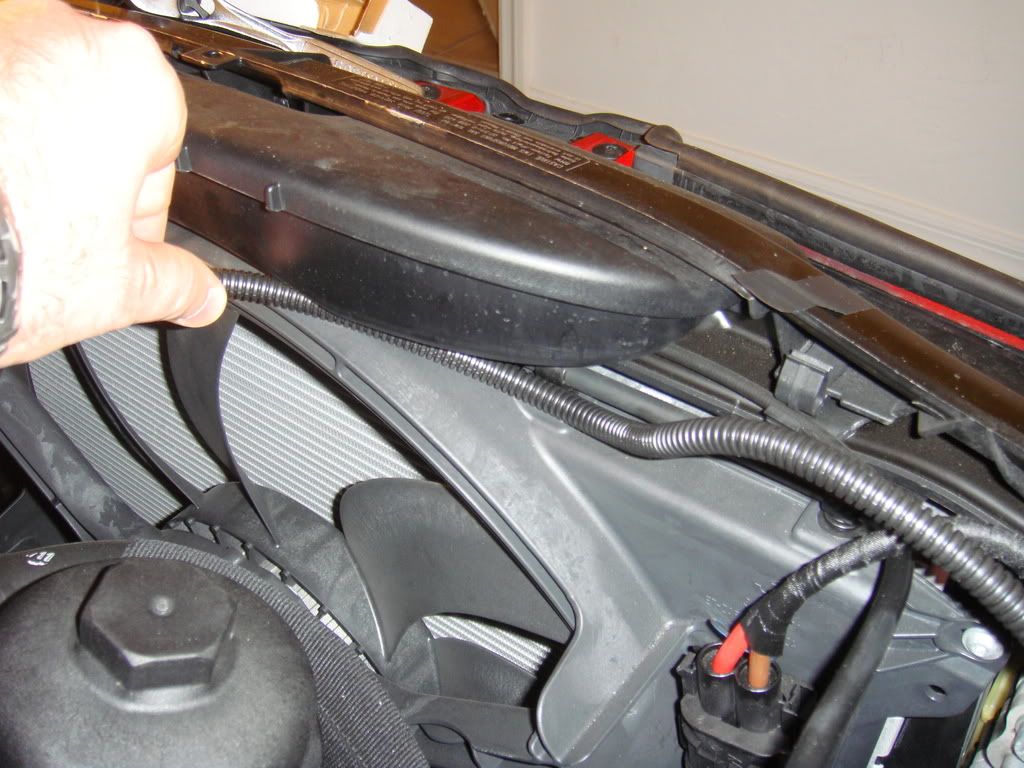 12. Repeat the same process for taking off the lid exposing the old bulb, taking out the bulb etc. Put in the new bulb on the other side and hook up the plug from the harness to the bulb. Lastly Place the resistor i supplied into the stock plug with the plug and play connector. Make sure yellow wire from my plug and the yellow wire (positive) from the car are connected on the same size  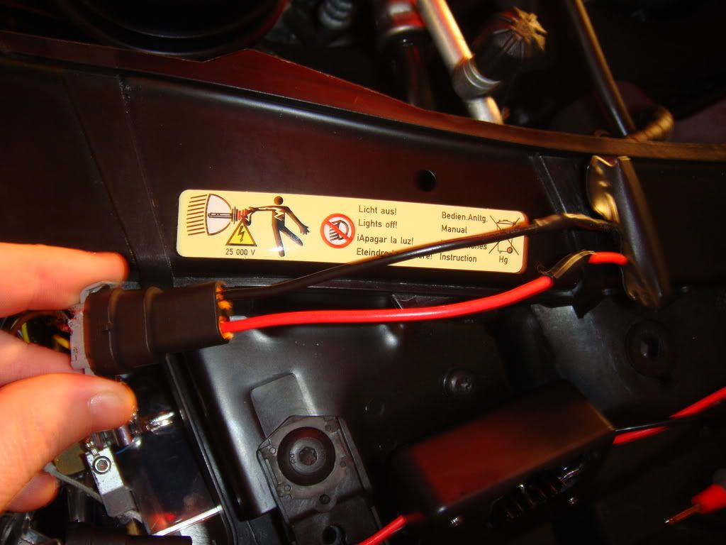 yours will be white dont forget 13. Lastly check all your connections and start up your car. Take a look and make sure your all done. WALLA! your done. Just tidy up your wires and zip tie any hanging wires. Here is the final look at the engine compartment. Looks stock and you wouldnt even know there is anything new if you didnt know to look for it  Enjoy your new super bright halos!!! Enjoy your new super bright halos!!!  Disclaimer: Im not responsible for any miss wiring or faulty connections and any damage that may occur from someone besides me installing this kit. Install at your own risk! Last edited by camaross305; 07-08-2009 at 02:06 PM.. |
| 07-06-2009, 10:20 PM | #2 |
|
Gruppe Titan


262
Rep 2,839
Posts
Drives: 08 E92 SG/Coral
Join Date: Sep 2007
Location: NC
|
This should help.
__________________
 Last edited by Amir87; 07-06-2009 at 10:37 PM.. |
|
Appreciate
0
|
| 07-07-2009, 12:46 PM | #5 | |
|
Ninja

390
Rep 4,014
Posts |
Quote:
__________________
2019 AW G30 530e l ZPP l ZMP l ZDH
Retired: 2016 F80 M3, 2012 E90 M3, 2008 535i |
|
|
Appreciate
0
|
| 07-08-2009, 03:23 PM | #9 | |
|
Major
 264
Rep 1,124
Posts |
Quote:
I guess I was the problem child of the first group because I ran into several roadblocks but I finally corrected all of them after hours of troubleshooting. It works now and they look great!!!  Here are some of the issues that I faced and for you to watch out: 1) The voltage for both posts (above picture) is 14 volts (checked with a meter). I left it bolted to the post on the right as shown in the picture. 2) Be sure the red and black wire are screwed in tightly in this unit. I realized the wires were loose and they came out after everything was connected. I was unable to see it because it was concealed with the closed lighting lid. 3) As mentioned previously (Step 8), it's very difficult to insert the bulbs (I have GP thunders 7500k) back into the housing unit with the harness. I found that it never screwed in tightly with the harness. The bulb and the housing have to be aligned properly (like a puzzle) for it to fit/screwed perfectly. On mine, the slots (to puzzle them together) were located at the 6:00, 9:00 and 12:00 clock position. So I inserted the bulbs WITHOUT the harness and it screwed in tightly without any light being released through any gaps. Afterwards, I connected the Elite Kit harness into the bulb. HOWEVER, BE CAREFUL TO NOT LET GO OF THE BULB DURING THIS PROCESS AND OF COURSE, NOT TO TOUCH THE BULB WITH YOUR FINGERS!! 4) Make sure both prongs of the resistor are inserted correctly and tightly into the OEM harness (Step 9). Make sure they don't bend inward. Anyway, the lights look great and NO ERRORS!!!  Last edited by choicez; 08-20-2009 at 09:05 PM.. |
|
|
Appreciate
0
|
| 07-08-2009, 04:03 PM | #10 |
|
MOAR POWERRRR
29
Rep 823
Posts |
I would of preferred to see a better in-line fuse to protect against the heat. The way it is right now, water could easily drip on the wires into the fuse holder. Doesn't help considering its facing downwards. Also in-line resistors to make it easier to fit into the headlight housing. I see that's how you had it in the first picture of the GB.
|
|
Appreciate
0
|
| 07-08-2009, 04:29 PM | #11 | |
|
135
Rep 1,825
Posts |
Quote:
 water should really mess with it anyway You could tuck it under the plastic protector though water should really mess with it anyway You could tuck it under the plastic protector though |
|
|
Appreciate
0
|
| 07-10-2009, 10:43 PM | #12 |
|
Ninja
390
Rep 4,014
Posts |
Alright, tried to install this kit...no go..not sure if it's different with e60's...(as it seems a lot of these aftermarket lighting products are)
everything was connected correctly (i'm no idiot), and yes I rechecked everything 3x...had error messages and none of the AE's turned on cam..check your pm please
__________________
2019 AW G30 530e l ZPP l ZMP l ZDH
Retired: 2016 F80 M3, 2012 E90 M3, 2008 535i |
|
Appreciate
0
|
| 07-12-2009, 10:54 PM | #13 |
|
MOAR POWERRRR
29
Rep 823
Posts |
I installed it last night and had a great deal of frustration trying to get:
1. the white connectors to fit onto the stock connector. It just didn't seem like a good match and it was bending the male prongs on the white connector in a bit, I had to keep removing them and pushing them apart. I was never able to get the stock clips to fit onto the white connector. I finally gave up after I busted my thumb trying to squeeze them together and used a ziptie to keep them tight. 2. the passenger side angel eye bulb is tightened to the left of the car. As it was noted above, it was near impossible for the wiring to turn the direction it needed to be in, in order for the prongs to fit in. I went ahead and installed it with out the connector on the bulb. After complete frustration I was able to finally get the bulb in but then realized the h8 connectors that came with the kit were too strong and would not bend and fit into the low clearance headlight housing. I had to take apart some of the excessive electrical tape in order to fit the connector on. The driver side portion went smooth, excluding the connecting of the resistor. I would of still preferred the resistor to not be perpendicular to the wires, but inline. It would of made it easier to fit inside of the headlight housing. I was tempted to unwrap the resistors and re-solder them inline but I was already too tired. Lastly, this is really a frustration but I realized while I was installing the power line that I shouldn't really be concerned about water getting into the fuse box but I should be worried about the heat from the engine melting my uncovered wires. Maybe the kits you sell from now on could relocate the fuse closer to the relay in order to get that away from the heat. Hmm last minute question, why was it required that you cut the wires from the black h8 connector that connected to the bulb? Were there already wires in the connectors you purchased? If that was the case were they not long enough to reach back to the relay? If so, I would recommend splicing/soldering the wires at a different place (instead of right at the connector) to make it easier to install inside the housing. BTW this is all constructive criticism and I hope it comes off that way. Just trying to save your future customers from complain about the same thing. The joys of early adoption. Overall it does exactly what it is supposed to do, and it looks hell of a lot brighter. |
|
Appreciate
0
|
| 07-14-2009, 03:47 AM | #14 |
|
Banned

620
Rep 2,013
Posts |
camaross305,
I sent you a PM a minute ago, but in case your PM box is full I'm also posting here. My car is the 2006 production year and after installation it throws an error. According to your instruction I have tried connecting yellow wire of your PnP plug to the brown wire of the OEM plug but in this case it doesn't work at all. If I connect the yellow wire of your PnP plug with the yellow from the OEM plug it works but throws an error. If anyone else has a pre March 2007 car and successfully installed the kit please chime in. Thanks. |
|
Appreciate
0
|
| 07-14-2009, 04:34 PM | #15 | |
|
Lieutenant
 28
Rep 495
Posts |
You are lucky. I have a 01/07 build. I got his instructions on yellow to brown and it did not work either. When I tried his other instructions per his email, my resistor went up in smoke (literally). So at least you got it to work.
 I would also like to hear from other pre-march build customers. Quote:
|
|
|
Appreciate
0
|
| 07-15-2009, 11:54 PM | #16 |
|
Colonel

350
Rep 2,937
Posts
Drives: 2013 Estoril 328i M Sport
Join Date: Oct 2007
Location: Beverly Hills, CA
|
Chris, the easiest way I found to "notch" the headlamp lids is to use a dremmel. It took 5 seconds with that tool and came out looking perfect.
|
|
Appreciate
0
|
| 07-16-2009, 11:17 PM | #17 |
|
Major
264
Rep 1,124
Posts |
If you're trying to match your fog lights, cornering lights, angel eyes and Xenons, click this link
http://www.e90post.com/forums/showth...271169&page=13 |
|
Appreciate
0
|
| 07-27-2009, 08:36 AM | #18 |
|
First Lieutenant

44
Rep 336
Posts |
Hey Camaross - I too am having major problems with the units.
I followed instructions exactly, have everything fitted nicely the same as your photos show. i have used the same positive and negative, but have no front lights working - my rear lights work fine. I too had problems with the red and black wires coming out of the units the same as choicez as shown, but more worryingly, my copper round thing has one leg broken off it, as you should see from the pics - could this be the reason my unit isn't working? I can feel heat coming through the resistors, so there is power getting to them - just no light. what do you think the issue could be? |
|
Appreciate
0
|
| 08-15-2009, 01:46 PM | #20 |
|
I found Jesus...He was Hiding behiind my Sofa
69
Rep 957
Posts |
Received yesterday and just finished the install. Other than the missing loom on the red power cable, zip ties, and my female connector wires were a white & a blue one (no matching black), the kit went together seamlessly in about an hour (including tiding up, etc.).
Thanks Chris and to those who posted on here as it WAS VERY helpful to have the diagram as well as to install the bulbs before plugging in. Here are my tiny contributions -I used a mirror to see that the small notch was on the top part (of the socket/ hole) as I didn't pay attn when removing the bulbs. -I placed the circuit board and resistors inside the light compartment BEFORE installing the bulb. There is plenty of room to the right (pax side) but it's easier to access when the bulb is out. -It was helpful to use a pull hook (Snap-on) to pull the driver side harness in between and underneath the cross bar to have an invisible install. It's definitely a nice improvement
__________________
|
|
Appreciate
0
|
| 08-17-2009, 03:18 PM | #21 |
|
Lieutenant
10
Rep 462
Posts |
AWESOME WRITE UP!! Makes this job look easy.
__________________
|
|
Appreciate
0
|
| 08-20-2009, 01:19 AM | #22 |
|
Brigadier General

198
Rep 4,647
Posts |
edited
__________________
SGE92TT......................... 12.331 Sec @ 117.89 Mph............................POWERED BY
l BMS DCI l HELIX IC l FORGE DVs l RR OCC & CP & SCOOPS l AR 3" DPs l AE QUADs l BLISTEIN PSS10 l P3 VENT GUAGE l VISHNU PROCEDE V5 AUTOTUNE l Lots of Window Stickers  Last edited by hun77777; 08-20-2009 at 04:16 PM.. |
|
Appreciate
0
|
Post Reply |
| Bookmarks |
|
|