Disassembly of old CCC Navigation Unit and Installation of new CIC Unit.
Using plastic pry-bar remove Center Dashboard trim. You can start from left side or right side.
Please be very careful not to make any scratches on the trim, neither break it.
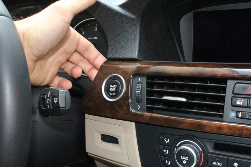

When you remove center console trim, unplug start/stop button
..
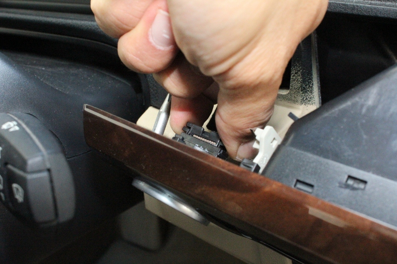
and DTC, flasher switch.
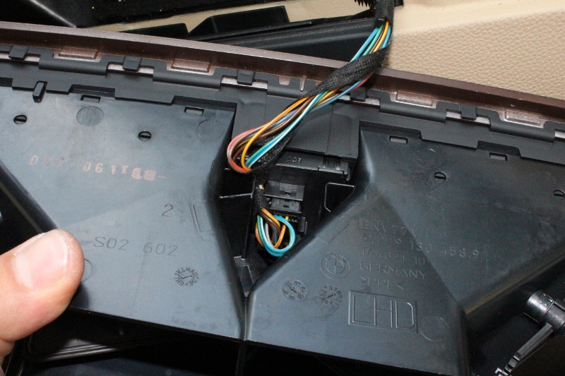
Place center dashboard trim on the side.
Next remove Air Condition Control Unit. Again you need to lift plastic trim with plastic pry-bar.
There are two clips on the left and right, which hold this AC controller in place.
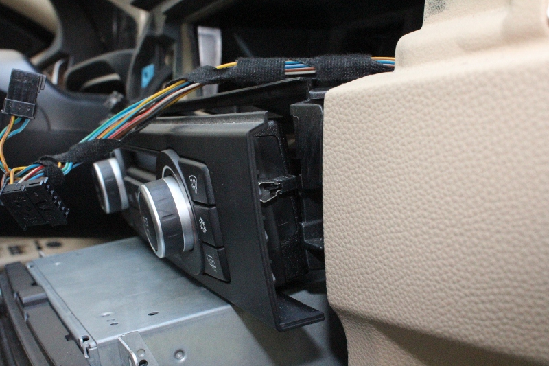
Unplug 3 sockets and again place AC Unit on the side.

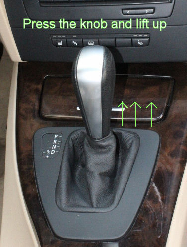
Next remove the shifter knob. You need to press the button and pull it straight off.
Then, remove old trim around the CCC Unit. Again you need to use plastic pry-bar.
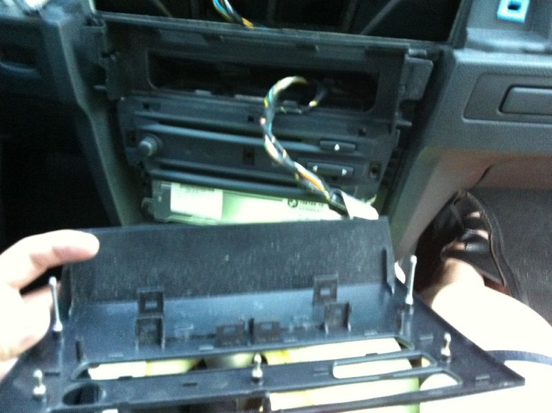
Unscrew 4 screws securing Navigation Unit.
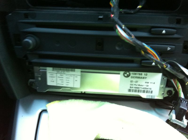
Unplug all connectors from CCC Unit.
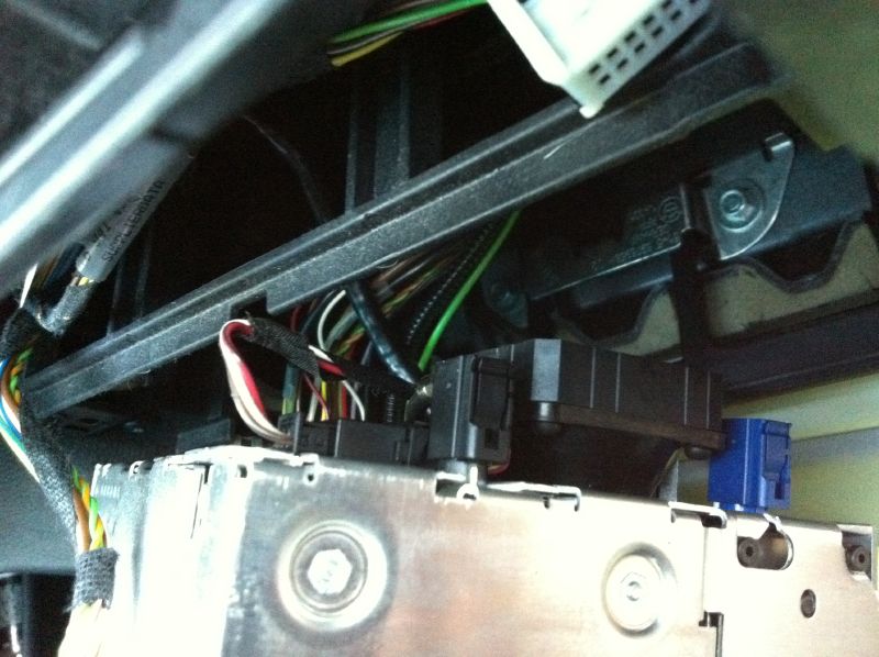
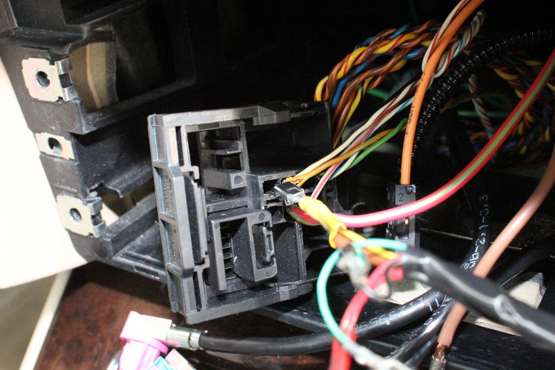
As to big radio square connector, you need to press down tab at the bottom of big socket and lift the handle up.

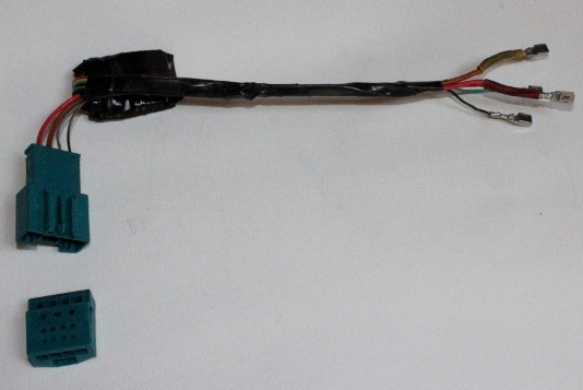
When all the connectors will be out and as well as CCC unit, it is time to connect EMULATOR (please note that there are different types of emulators and way how to connect them).
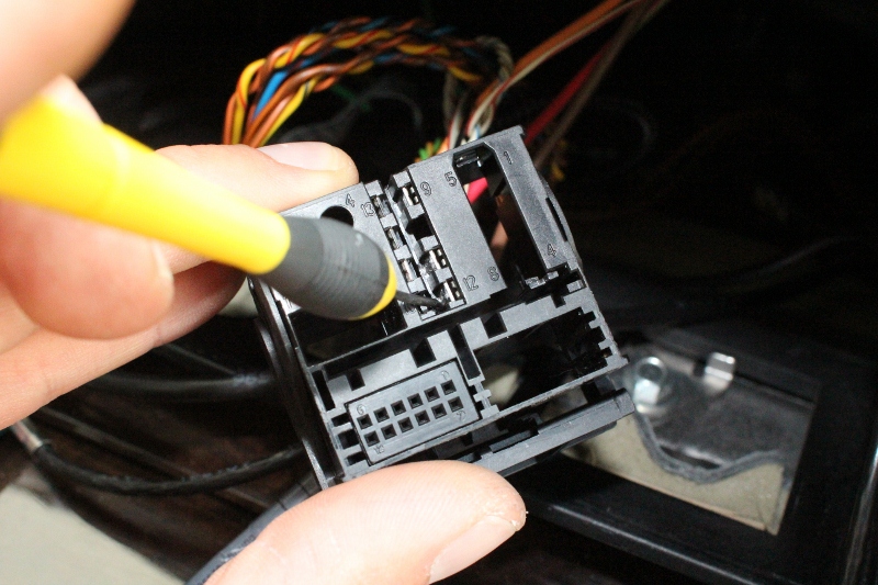
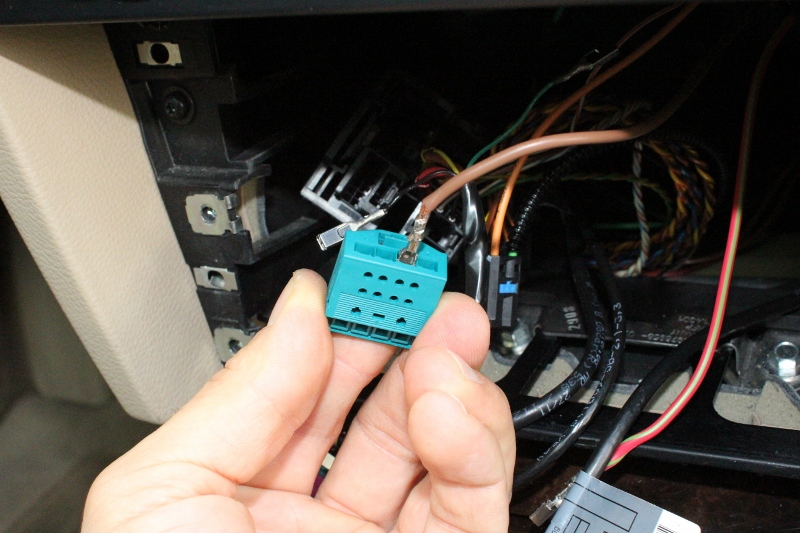
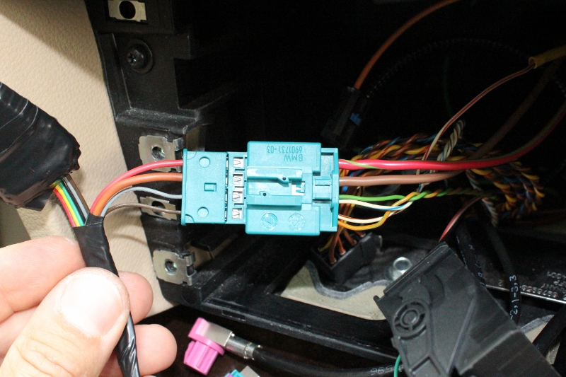
Start again from square socket form CCC unit and find the top of it.
Using small screwdriver, press down the tab
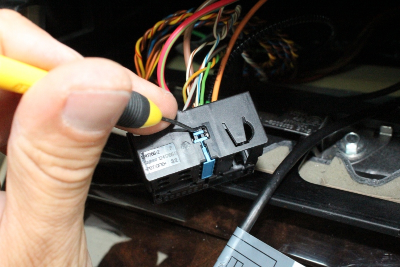
and lift up the blue plug.
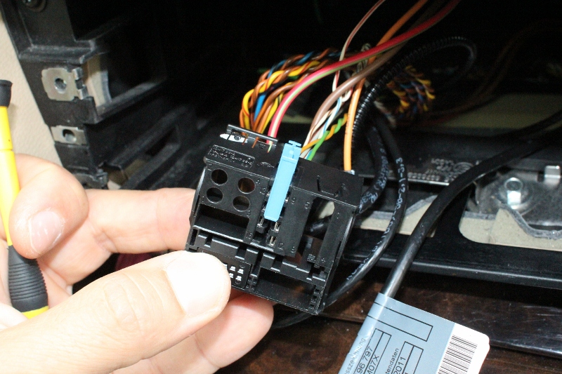
Now you have gained access to pins (9,11,12, 15). Start removing them one by one.
Lets start from removing pin 12 (Ground)
Again you will need small screwdriver to press down small tab on a side of the pin and in the same time start pulling out from the other side brown wire. Dont use too much force. When you press the tab correctly, you should be able to remove this wire without problems.
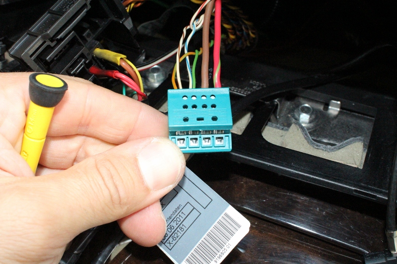
When the brown wire will be out, take in hand empty socket attached to emulator harness and plug it into the hole #3.
Now it is time to insert one of the four wires attached to emulator. Brown wire with yellow ending goes into PIN 12 (the same hole which you have just emptied). Push this wire until you will hear a click.
Do the same procedure with pin #15. Remove red wire from the navigation socket, next insert it into hole #4 from provided socket.

Finally insert Red wire with the red ending from emulator harness into the same hole #15 in Navi socket.
Good job, there are two more wires left to replace. Remove Pin 9 (Green wire) from Navigation socket and plug it into the same hole green wire from the emulator harness.

The Green wire which you have just removed from Pin 9 should be plug in the hole #2 from the provided socket. Dont suggest much with my photo because I have additional wires connected to PIN 9 and 11.
Finally remove Brown wire with green stripe from Pin 11 and in the empty hole plug black wire from emulator harness. The wire which you have just disconnected from square socket should be plug into the hole #1 from the provided socket.
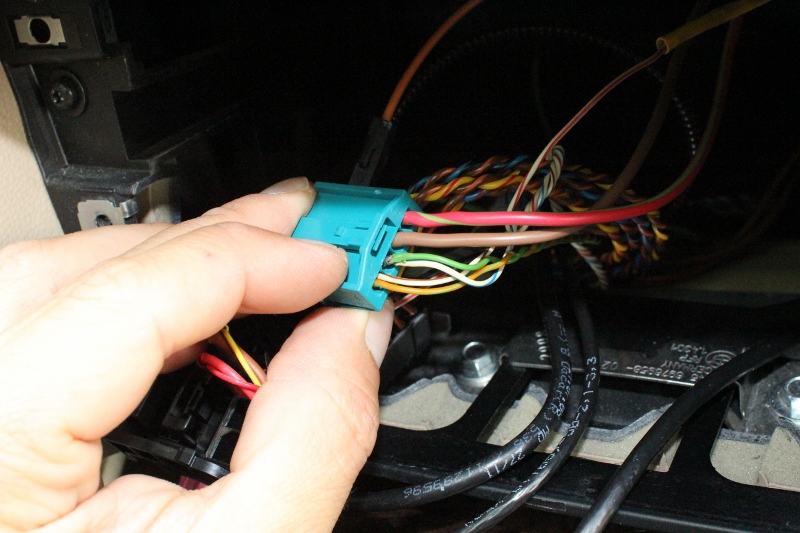
In the end , your new socket should looks like this. Again, please ignore my additional white wires in the holes 1 and 2.
Press down the tab to lock the socket and you are ready to insert plug into socket.
Please double check if you have connected wires is the same way like at the above photo.
Dont forget to insert back blue security tab.
