Confirming the S65 Bearing Issue
For the next two years, word of the bearing clearance issue began to spread slowly, and understandably met some resistence. Since the 2011 discovery, many more engine failures have occurred, and many of them are on low mileage engines. Now that many engines are outside of warranty, the number of failures is beginning to accelerate on higher mileage engines. When bearings photos are posted, they seem to have all the same tell-tale signs seen in the photos above -- signs of oil starvation due to inadequate journal/bearing clearance.
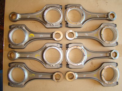
With a few upcoming engine builds in planning or already in process, I thought it would be a good idea to confirm the original 2011 findings. I would take two factory crankshafts, two sets of connecting rods, fresh factory bearings, and two sets of used bearings from disassembled engines. We would convene at Van Dyne Engineering and see if we could duplicate the results.
Testing Methodology:
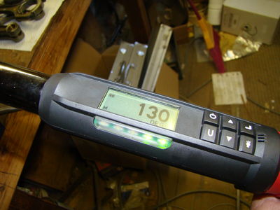
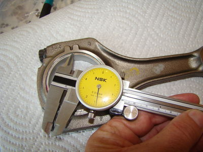
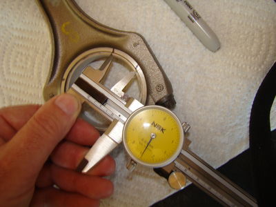
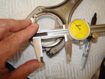
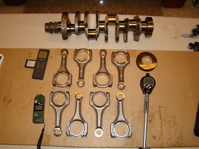
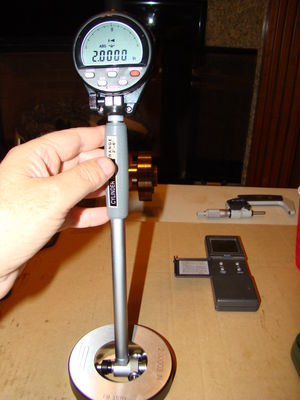
Tests would be conducted in the Van Dyne engine clean room, at room temperatures (approximately 74 degrees). To ensure measurement consistency, all crankshafts, rods, and measuring equipment sat in this environment for two hours before any measurements were taken. Three micrometers were calibrated using a 2-inch x 1/2-inch calibration block. All three micrometers would test the same crankshaft journals. All micrometers confirmed the same measurements. Each measurement was taken three times each to eliminate any possible variance due to equipment position, angle, etc. Once the three micrometers each validated the crank journals, the rod bearing "bore gauge" was calibrated to the micrometer. Each rod and bearing combination was torqued to exact factory specifications with new rod bolts, and proper rod bolt lubrication. Each rod bore was measured and verified three times to eliminate possible variance.
The Confirmed Results:
We confirmed the following results with the used bearings (same bearings removed from the engine with the same crankshaft). Keep in mind, these are the exact bearings that came out of this engine. This is what the clearance measured on the running engine with 30,000 miles.
| Cyl-1 | Cyl-2 | Cyl-3 | Cyl-4 | Cyl-5 | Cyl-6 | Cyl-7 | Cyl-8 |
| Crank-1, Rod Journals | 2.04655 | 2.04650 | 2.04655 | 2.04660 | 2.04650 | 2.04655 | 2.04660 | 2.04650 |
| Crank-1, Rod/Bearing Bore | 2.04800 | 2.04780 | 2.04835 | 2.04780 | 2.04780 | 2.04780 | 2.04835 | 2.04780 |
| Crank-1 Bearing Clearance | 0.00145 | 0.00130 | 0.00180 | 0.00120 | 0.00130 | 0.00125 | 0.00175 | 0.00130 |
Notice Cylinder #3 and Cylinder #4. These two are at the opposite ends of the clearance spectrum. As a verification process, we swapped the bearings between these two rods, retorqued them to factory specifications, and took the measurements again. This would guarantee whether or not we had an anomaly with rod journal bore, or bearing thickness. Our measurements after swapping the bearings showed the same exact values and proved the rod bearing bore and not bearing thickness was causing these clearance variances.
In our next test, we replaced the Cylinder #4 rod with a brand new factory bearing. We re-torqued and remeasured. Then using our measurements, generated this table of clearances as if all cylinders had new bearings.
| Cyl-1 | Cyl-2 | Cyl-3 | Cyl-4 | Cyl-5 | Cyl-6 | Cyl-7 | Cyl-8 |
| Crank-1, Rod Journals | 2.04655 | 2.04650 | 2.04655 | 2.04660 | 2.04650 | 2.04655 | 2.04660 | 2.04650 |
| Crank-1, Rod/(New) Bearing | 2.04800 | 2.04800 | 2.04800 | 2.04800 | 2.04800 | 2.04800 | 2.04800 | 2.04800 |
| Crank-1 Bearing Clearance | 0.00145 | 0.00150 | 0.00145 | 0.00140 | 0.00150 | 0.00145 | 0.00140 | 0.00150 |
Still using Crank #1, next we tested Carrillo connecting rods and another set of used bearings. This test is much less scientific than the previous one, but it provides a good cross reference to see if the Carrillo's have a similar bore size variance as the factory connecting rods. Since the Carrillo rod bolts are different, we made sure to follow the Carrillo torque specifications and use the exact thread/head lubricant they recommended.
| Cyl-1 | Cyl-2 | Cyl-3 | Cyl-4 | Cyl-5 | Cyl-6 | Cyl-7 | Cyl-8 |
| Crank-1, Rod Journals | 2.04655 | 2.04650 | 2.04655 | 2.04660 | 2.04650 | 2.04655 | 2.04660 | 2.04650 |
| Crank-1, Carrillo Rod/Bearing | 2.04790 | 2.04780 | 2.04775 | 2.04780 | 2.04780 | 2.04780 | 2.04780 | 2.04795 |
| Crank-1 Bearing Clearance | 0.00135 | 0.00130 | 0.00120 | 0.00120 | 0.00130 | 0.00125 | 0.00120 | 0.00145 |
For completeness and redundancy, here's the same measurements with Crankshaft #2.
| Cyl-1 | Cyl-2 | Cyl-3 | Cyl-4 | Cyl-5 | Cyl-6 | Cyl-7 | Cyl-8 |
| Crank-2, Rod Journals | 2.04655 | 2.04650 | 2.04660 | 2.04650 | 2.04650 | 2.04655 | 2.04660 | 2.04650 |
| Crank-2, Rod/Bearing Bore | 2.04800 | 2.04780 | 2.04835 | 2.04780 | 2.04780 | 2.04780 | 2.04835 | 2.04780 |
| Crank-2 Bearing Clearance | 0.00145 | 0.00130 | 0.00175 | 0.00130 | 0.00130 | 0.00125 | 0.00175 | 0.00130 |
| Cyl-1 | Cyl-2 | Cyl-3 | Cyl-4 | Cyl-5 | Cyl-6 | Cyl-7 | Cyl-8 |
| Crank-2, Rod Journals | 2.04655 | 2.04650 | 2.04660 | 2.04650 | 2.04650 | 2.04655 | 2.04660 | 2.04650 |
| Crank-2, Carrillo Rod/Bearing | 2.04790 | 2.04780 | 2.04775 | 2.04780 | 2.04780 | 2.04780 | 2.04780 | 2.04795 |
| Crank-2 Bearing Clearance | 0.00135 | 0.00130 | 0.00115 | 0.00130 | 0.00130 | 0.00125 | 0.00120 | 0.00145 |
Detonation vs. Bearing Wear: Could this be the cause?
By Kawasaki00
Regular Guy sent me a complete set of rods bearings and pistons to document out of a STOCK engine.
The purpose of this post is to address the detonation. What was found is that there is no significant detonation leading to bearing wear on this engine. Not saying some engines may not have it but this engine does not.
Examples of bearing wear due to detonation:
The first two pictures are reference from another type of engine that has too much timing and detonation. The shiny spots on the rod and silver specs on the back of the bearings are what happens to a rod bearing when it is moving around in the rod under load. The bearing actually lifts off the rod, oil gets behind it and then when it is slammed back down again this is what causes the silver specs from fretting.
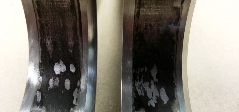
 Comparing to this motor:
You can see the picture of the complete set of rods that the oil stain has not penetrated the back side of the bearing and discolored the rod. This means that at no time has the rod bearing deformed to the point that is lifts out of the rod itself. The back of the rod bearing also shows the same thing, there is also no fretting on the back of the bearing.

 Where does detonation show?
The first place that detonation will show up is in the pin bore of the piston and the bushing of the rod.
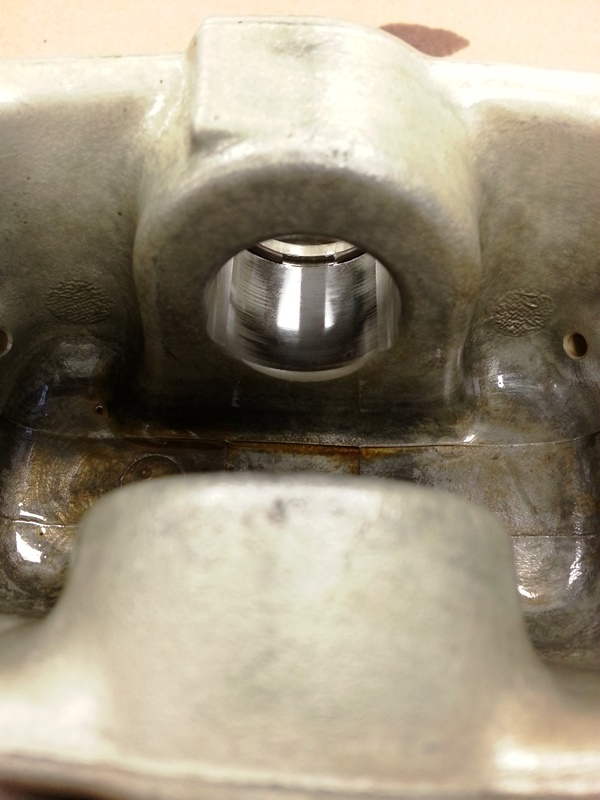
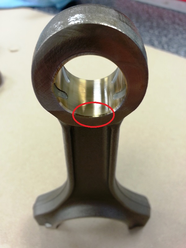
There is no evidence of heat in the pin bores nor rainbow effect in the bushings. What I have circled on the rod pinbore is the area where when the engine is detonating it will beat the brass out the side like mushing the filling out of a doughnut. There is nothing to show this engine has been detonating to the point that is would cause any type of rod bearing wear.
Do the piston tops show detonation?
As far as the piston tops, well they have alot of build up. This can be from one of two things, too much blowby due to loose rings or on a street engine from the emission system dumping oil back into the intake side. Without having the entire engine to look at it is hard to say. I have noticed in the past that certain oils also do this. I wont place judjment on that as that will certainly erupt a brand war on here.

The second ring shows very good seal as it is only worn about 1/4 of the ring. When there is poor sealing that second ring will wear all the way across the face.
 Conclusions:
In conclusion there is no detonation in this engine. Failure analysis and teardown documentation is something we do regularly. The findings are conclusive with other people and they are what they are to put it into a nutshell.
In the next couple days i will post the specs from the older rod bearings and will also post the numbers from a fresh set of bearings that are fit up ready to run.
Great Bearing Measurements of 2014
Preparation for clearance measurements
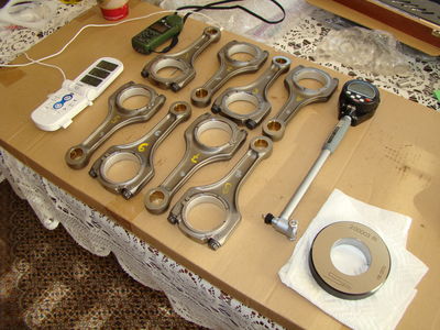
I wanted the clearance measurements to be as controlled as possible. To me, this meant following the manufacturer’s specification and maintaining a proper and controlled temperature environment. Each bearing was installed in the rod and the rod bolts were properly stretched. The fitted rods were placed out on an open table along with the measuring equipment for two hours before measuring. The room temperatures were set to approximately 74-77 degrees Fahrenheit to match the conditions at Van Dyne Engineering during the original tests. (To be honest, I didn't have my portable weather gauge with me at Van Dyne during the original tests, so I'm only guestimating the original temperature.) I am hoping these procedures will gain uniformity between all of the temperatures, measurements, and measuring equipment.
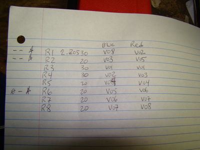
Selecting bearing pairs to match rod bearing bores
I wanted to simulate the possible effects of tolerance stack up. So before beginning to assemble the rods and bearings, I had previously measured all of the rod bearing bores. These measurements were as follows:
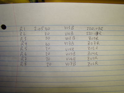
| R1 | R2 | R3 | R4 | R5 | R6 | R7 | R8 | MIN | Max | Official | Min Dev. | Max Dev. |
| Rod B.E. Bore | 2.20530 | 2.20520 | 2.20520 | 2.20530 | 2.20530 | 2.20520 | 2.20520 | 2.20520 | 2.20520 | 2.20530 | 2.20520 | 0.00000 | 0.00010 |
| Rod B.E. Thickness | 0.72505 | 0.72515 | 0.72445 | 0.72500 | 0.72480 | 0.72520 | 0.72465 | 0.72450 | 0.72445 | 0.72520 | 0.72500 | -0.00055 | 0.00020 |
To simulate the tolerance stack up, I wanted to select bearings as described below. Since it might not be possible to simulate all combinations, the following table describes my order of preference.
- Small rod bore + thicker bearings
- Small rod bore + nominal bearings
- Nominal rod bore + nominal bearings
- Large rod bore + thicker bearings
- Large rod bore + nominal bearings
- Nominal rod bore + thicker bearings
Using these criteria above, I came up with the following rod/bearing combinations.
| 702/703 Stack Up | R1 | R2 | R3 | R4 | R5 | R6 | R7 | R8 | MIN | Max | Official | Min Dev. | Max Dev. |
| Rod B.E. Bore | 2.20530 | 2.20520 | 2.20520 | 2.20530 | 2.20530 | 2.20520 | 2.20520 | 2.20520 | 2.20520 | 2.20530 | 2.20520 | 0.00000 | 0.00010 |
| Top (Blue) | 0.07870 | 0.07870 | 0.07865 | 0.07865 | 0.07865 | 0.07865 | 0.07865 | 0.07865 | 0.07865 | 0.07870 | 0.07865 | 0.00000 | 0.00005 |
| Bottom (Red) | 0.07855 | 0.07855 | 0.07850 | 0.07850 | 0.07850 | 0.07855 | 0.07850 | 0.07850 | 0.07850 | 0.07855 | 0.07850 | 0.00000 | 0.00005 |
| Combined Thickness | 0.15725 | 0.15725 | 0.15715 | 0.15715 | 0.15715 | 0.15720 | 0.15715 | 0.15715 | 0.15715 | 0.15725 | 0.15715 | 0.00000 | 0.00010 |
| Bore - CT | 2.04805 | 2.04795 | 2.04805 | 2.04815 | 2.04815 | 2.04800 | 2.04805 | 2.04805 | 2.04795 | 2.04815 | 2.04805 | -0.00010 | 0.00010 |
| Bearing ID's (top/bottom) | V08/V02 | V03/V05 | V01/V01 | V02/V03 | V04/V04 | V05/V06 | V06/V07 | V07/V08 | | | | | |
| 088/089 Stack Up | R1 | R2 | R3 | R4 | R5 | R6 | R7 | R8 | MIN | Max | Official | Min Dev. | Max Dev. |
| Rod B.E. Bore | 2.20530 | 2.20520 | 2.20520 | 2.20530 | 2.20530 | 2.20520 | 2.20520 | 2.20520 | 2.20520 | 2.20530 | 2.20520 | 0.00000 | 0.00010 |
| Top (Blue) | 0.07890 | 0.07890 | 0.07885 | 0.07880 | 0.07885 | 0.07885 | 0.07885 | 0.07885 | 0.07880 | 0.07890 | 0.07885 | -0.00005 | 0.00005 |
| Bottom (Red) | 0.07875 | 0.07880 | 0.07860 | 0.07860 | 0.07865 | 0.07865 | 0.07865 | 0.07865 | 0.07860 | 0.07880 | 0.07865 | -0.00005 | 0.00015 |
| Combined Thickness | 0.15765 | 0.15770 | 0.15745 | 0.15740 | 0.15750 | 0.15750 | 0.15750 | 0.15750 | 0.15740 | 0.15770 | 0.15750 | -0.00010 | 0.00020 |
| Bore - CT | 2.04765 | 2.04750 | 2.04775 | 2.04790 | 2.04780 | 2.04770 | 2.04770 | 2.04770 | 2.04750 | 2.04790 | 2.04770 | -0.00020 | 0.00020 |
| Bearing ID's (top/bottom) | V03/220.07 | V01/220.03 | V02/Z03 | V08/Z07 | V04/Z02 | V05/Z04 | V06/Z05 | V07/Z06 | | | | | |
 Stretching rod bolts and installing bearings
Both sets of bearings (702/703 and 088/089) were given new rod bolts so the tests would be as equal as possible. New S65 rod bolts must be stretched before use. The stretching procedure is very specific. You must torque and release two times prior to final torque and use. The following procedure is documented in the BMS TIS guide for building the S65 engine.
| Replace screws Screws washed and oiled | |
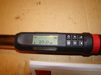
| 1. Jointing torque | 6 Nm |
| 2. Setting torque | 20 Nm |
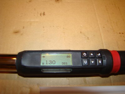
| 3. Angle of rotation | 130-Degrees |
| Important 4. Release connecting rod bolts. | |
| 5. Jointing torque | 6 Nm |
| 6. Setting torque | 20 Nm |
| 7. Angle of rotation | 130-Degrees |
| Important 8. Release connecting rod bolts. | |
| 9. Jointing torque | 6 Nm |
| 10. Setting torque | 20 Nm |
| 11. Angle of rotation | 130-Degrees |
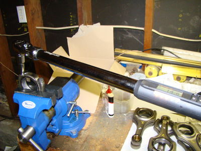
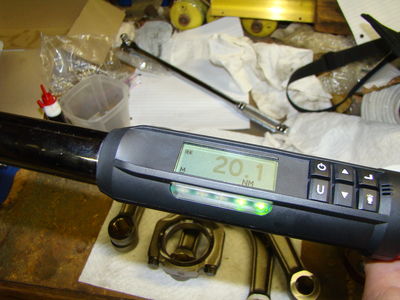
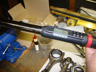
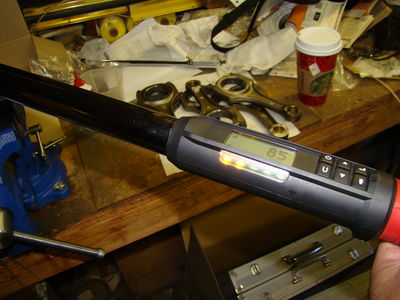
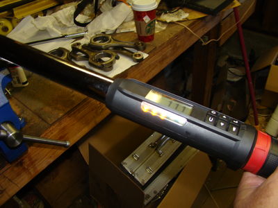
This procedure would normally require two different tools. First you would need to use the torque wrench to torque to 6 NM then 20 NM. Second you would need to change to the torque angle gauge. The pictures below show the procedure with a normal (albeit electronic) torque wrench + torque angle gauge.
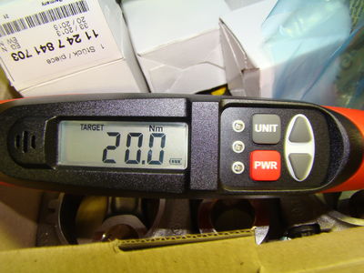
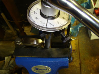
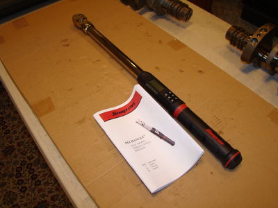
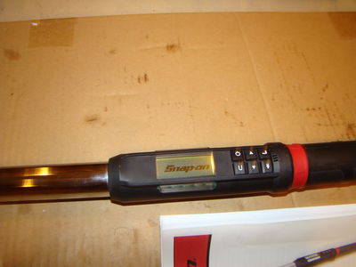
The normal procedure shown above is good, but is prone to minor errors. That type of torque angle gauge is can slip a little -- making the torque angle less accurate. This error happened to me repeatedly while stretching the rod bolts. So before the final rod bolt stretch, I decided it was time to upgrade my torque wrench anyways. I bought the all-in-one electronic
Snapon ATECH3FR250B TECHANGLE torque wrench/torque angle gauge. This is a very nice torque wrench that is capable of switching between torque and torque angle. The electronics in the device make it possible to switch between units of torque at the press of a button (ft-lbs, in-lbs, Nm, dNm, Kcgm, and torque angle). The wrench supports different pre-sets too. So I was able to set the 20 Nm on one setting, then hit the button and switch to 130 degree torque angle. With this tool, there is no need to switch between two different devices.
Before the final stretch, all the rod bolts were completely removed. Each bolt was re-oiled, and the rod bolt under-cap was re-oiled as well. This ensures no galling could take place and an accurate final setting. The vice is also fitted with hard rubber boots to prevent damage to the connecting rods when they are clamped in.
 Final Preparations
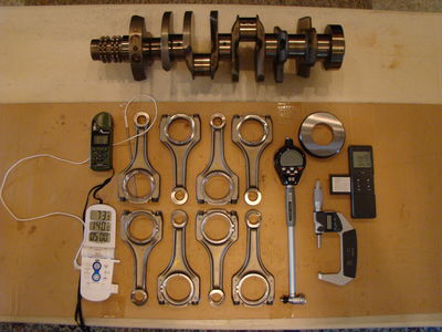
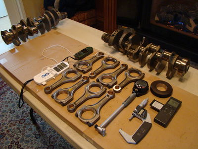
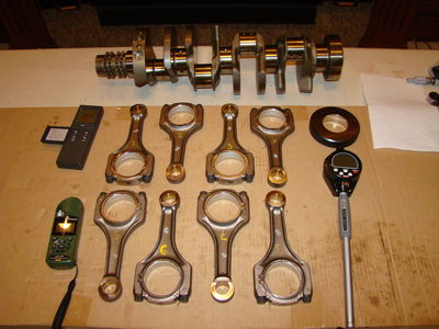
I'm almost ready to begin measuring. There's just a few more things I need to do. I promised to provide eccentricity measurements, so I need to mark the connecting rods at 5, 45, 90, 135, and 175 degrees.
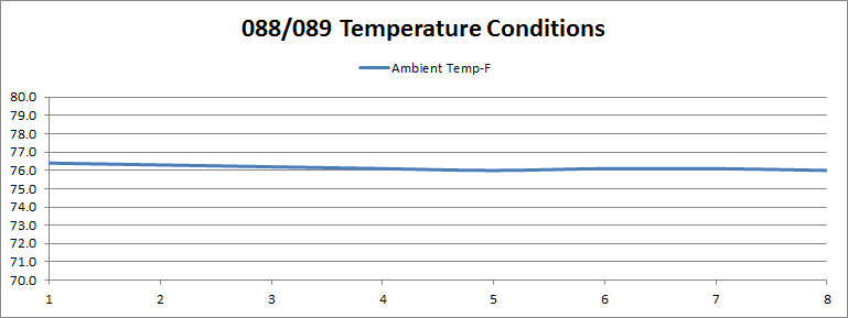
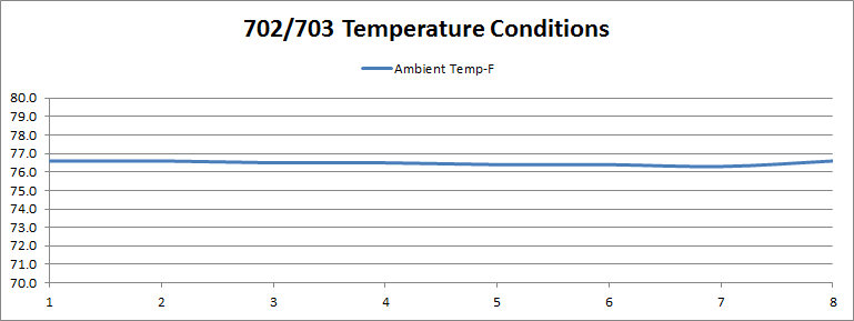
Before measuring, I let all of the rods sit for two hours in the open air room temperature with thermostat set to ~76 degrees. The measuring equipment sits at the same location at the same temperatures. The Kestrel 4500 portable weather station is the small green device sitting on the lower left near rod #5 in the first photo, and upper left near rod #1 in the second photo. You see these on TV shows like Deadliest Catch. They are very nice and very accurate. This particular model will data log all environmental conditions and allows me to take individual snapshots in addition to a continuous data logs.
Last but not least, after letting everything sit for a few hours, I re-measured the crankshaft journals. No surprises here, they measured exactly the same as before, although in a different order. By that I mean, the measurement spread was identical to before, but the measurements seemed to change order on the journals. When you're talking about measuring tenths (0.00010 inch) and half-tenths (0.00005 inch), I'm told this is quite normal. Just to make sure, I called Van Dyne for advice. Van Dyne told me: "If you try to understand it and don't ignore it, you'll never get anything done."
| Crank Journals | R1 | R2 | R3 | R4 | R5 | R6 | R7 | R8 | MIN | Max | Official | Min Dev. | Max Dev. |
| New | 2.04655 | 2.04660 | 2.04660 | 2.04655 | 2.04655 | 2.04655 | 2.04655 | 2.04650 | 2.04650 | 2.04660 | 2.04655 | -0.00005 | 0.00005 |
| Old | 2.04655 | 2.04650 | 2.04655 | 2.04660 | 2.04650 | 2.04655 | 2.04660 | 2.04650 | 2.04650 | 2.04660 | 2.04655 | -0.00005 | 0.00005 |
The Results:
088/089 Bearing Clearances
Calibration and set up:
| 088/089 Results | R1 | R2 | R3 | R4 | R5 | R6 | R7 | R8 | MIN | Max | Official | Min Dev. | Max Dev. |
| Rod B.E. Bore | 2.20530 | 2.20520 | 2.20520 | 2.20530 | 2.20530 | 2.20520 | 2.20520 | 2.20520 | 2.20520 | 2.20530 | 2.20520 | 0.00000 | 0.00010 |
| Top (Blue) | 0.07890 | 0.07890 | 0.07885 | 0.07880 | 0.07885 | 0.07885 | 0.07885 | 0.07885 | 0.07880 | 0.07890 | 0.07885 | -0.00005 | 0.00005 |
| Bottom (Red) | 0.07875 | 0.07880 | 0.07860 | 0.07860 | 0.07865 | 0.07865 | 0.07865 | 0.07865 | 0.07860 | 0.07880 | 0.07865 | -0.00005 | 0.00015 |
| Combined Thickness | 0.15765 | 0.15770 | 0.15745 | 0.15740 | 0.15750 | 0.15750 | 0.15750 | 0.15750 | 0.15740 | 0.15770 | 0.15750 | -0.00010 | 0.00020 |
| Bore - CT | 2.04765 | 2.04750 | 2.04775 | 2.04790 | 2.04780 | 2.04770 | 2.04770 | 2.04770 | 2.04750 | 2.04790 | 2.04770 | -0.00020 | 0.00020 |
| Bearing Measurements | 2.04785 | 2.04790 | 2.04795 | 2.04795 | 2.04800 | 2.04795 | 2.04800 | 2.04800 | 2.04785 | 2.04800 | 2.04795 | -0.00010 | 0.00005 |
| Nominal Bearing Clearance | 0.00130 | 0.00135 | 0.00140 | 0.00140 | 0.00145 | 0.00140 | 0.00145 | 0.00145 | 0.00130 | 0.00145 | 0.00140 | -0.00015 | 0.00010 |
| Min Stack Up Clearance | 0.00125 | 0.00130 | 0.00135 | 0.00135 | 0.00140 | 0.00135 | 0.00140 | 0.00140 | 0.00125 | | | | |
| Max Stack Up Clearance | 0.00135 | 0.00140 | 0.00145 | 0.00145 | 0.00150 | 0.00145 | 0.00150 | 0.00150 | | 0.00150 | | | |
| Bearing ID's (top/bottom) | V03/220.07 | V01/220.03 | V02/Z03 | V08/Z07 | V04/Z02 | V05/Z04 | V06/Z05 | V07/Z06 | | | | | |
| Bearing ID Photos | | | | | | | | | | | | | |
| Clearance Photos | | | | | | | | | | | | | |
Official 088/089 Bearing Thickness and Clearance Specifications
| Engine | S65B40 | |
| Bearing Dimensions (088/089 Bearings) | Metric Dimensions | SAE (Inch) Dimensions |
| Rod + Bearing Dimensions | 52.0180 mm | 2.04795 inch |
| Rod + Bearing Variance (1) | 52.0141 - 52.0281 mm | 2.04780 - 2.04835 inch |
| Nominal Rod Bearing Clearance | 0.0357 mm | 0.00140 inch |
| Bearing Clearance Variance (1) | 0.0305 - 0.0470 mm | 0.00120 - 00185 inch |
| Bearing Clearance Tolerance | -0.0051 - +0.0114 mm | -0.00020, +0.00045 inch |
| Bearing Clearance per Journal inch | | 0.00068 inch/inch |
| Bearing Clearance per Journal Inch Variance (1) | | 0.00059 - 0.00090 inch/inch |
| Nominal Bearing Thickness (Top, Blue) | 2.0028 mm | 0.07885 inch |
| Nominal Bearing Thickness (Bottom, Red) | 1.9977 mm | 0.07865 inch |
| Bearing Thickness Variance (Top, Blue) | 2.0015 - 2.0041 mm | 0.07880 - 0.07890 inch |
| Bearing Thickness Variance (Bottom, Red) | 1.9964 - 2.0015 mm | 0.07860 - 0.07880 inch |
| Bearing Tolerance (Top, Blue) | -0.0013, +0.0013 mm | -0.00005, +0.00005 inch |
| Bearing Tolerance (Bottom, Red) | -0.0013, +0.0038 mm | -0.00005, +0.00015 inch |
Notes: (1) Includes previous measurement results from Van Dyne Engineering
When comparing to the original Van Dyne measurements, there seem to be no surprises here. The crankshaft journals measured within the same ranges, as did the connecting rod + bearing assemblies. With the addition of the newer virgin 089 bearings, I have changed the "official" estimate of 0.00125 inch clearance to 0.00140 inch clearance. That's a 0.00015 inch increase over the previous nominal measurements. That increases the nominal clearance-to-journal/inch ratio from 0.00061 inch/inch to 0.00068 inch/inch, which is still lower than the minimum Clevite recommendation of 0.00075 inch/inch.
702/703 Bearing Clearances
Calibration and set up:
| 702/703 Results | R1 | R2 | R3 | R4 | R5 | R6 | R7 | R8 | MIN | Max | Official | Min Dev. | Max Dev. |
| Rod B.E. Bore | 2.20530 | 2.20520 | 2.20520 | 2.20530 | 2.20530 | 2.20520 | 2.20520 | 2.20520 | 2.20520 | 2.20530 | 2.20520 | 0.00000 | 0.00010 |
| Top (Blue) | 0.07870 | 0.07870 | 0.07865 | 0.07865 | 0.07865 | 0.07865 | 0.07865 | 0.07865 | 0.07865 | 0.07870 | 0.07865 | 0.00000 | 0.00005 |
| Bottom (Red) | 0.07855 | 0.07855 | 0.07850 | 0.07850 | 0.07850 | 0.07855 | 0.07850 | 0.07850 | 0.07850 | 0.07855 | 0.07850 | 0.00000 | 0.00005 |
| Combined Thickness | 0.15725 | 0.15725 | 0.15715 | 0.15715 | 0.15715 | 0.15720 | 0.15715 | 0.15715 | 0.15715 | 0.15725 | 0.15715 | 0.00000 | 0.00010 |
| Bore - CT | 2.04805 | 2.04795 | 2.04805 | 2.04815 | 2.04815 | 2.04800 | 2.04805 | 2.04805 | 2.04795 | 2.04815 | 2.04805 | -0.00010 | 0.00010 |
| Bearing Measurements | 2.04830 | 2.04815 | 2.04840 | 2.04820 | 2.04835 | 2.04830 | 2.04820 | 2.04820 | 2.04815 | 2.04840 | 2.04820 | -0.00005 | 0.00020 |
| Nominal Bearing Clearance | 0.00175 | 0.00160 | 0.00185 | 0.00165 | 0.00180 | 0.00175 | 0.00165 | 0.00165 | 0.00160 | 0.00185 | 0.00165 | -0.00010 | 0.00025 |
| Min Stack Up Clearance | 0.00170 | 0.00155 | 0.00180 | 0.00160 | 0.00175 | 0.00170 | 0.00160 | 0.00160 | 0.00155 | | | | |
| Max Stack Up Clearance | 0.00180 | 0.00165 | 0.00190 | 0.00170 | 0.00185 | 0.00180 | 0.00170 | 0.00170 | | 0.00190 | | | |
| Bearing ID's (top/bottom) | V08/V02 | V03/V05 | V01/V01 | V02/V03 | V04/V04 | V05/V06 | V06/V07 | V07/V08 | | | | | |
| Bearing ID Photos | | | | | | | | | | | | | |
| Clearance Photos | | | | | | | | | | | | | |
Official 702/703 Bearing Thickness and Clearance Specifications
| Engine | S65B40 | |
| Bearing Dimensions (702/703 Bearings) | Metric Dimensions | SAE (Inch) Dimensions |
| Rod + Bearing Dimensions | 52.0243 mm | 2.04820 inch |
| Rod + Bearing Variance | 52.0230 - 52.0294mm | 2.04815 - 2.04840 inch |
| Nominal Rod Bearing Clearance | 0.0419 mm | 0.00165 inch |
| Bearing Clearance Variance | 0.0394 - 0.0483 mm | 0.00155 - 0.00190 inch |
| Bearing Clearance Tolerance | -0.0025 - +0.0064 mm | -.00010 - 0.00025 inch |
| Bearing Clearance per Journal inch | | 0.00081 inch/inch |
| Bearing Clearance per Journal Inch Variance | | 0.00076 - 0.00093 inch/inch |
| Nominal Bearing Thickness (Top, Blue) | 1.9977 mm | 0.07865 inch |
| Nominal Bearing Thickness (Bottom, Red) | 1.9939 mm | 0.07850 inch |
| Bearing Thickness Variance (Top, Blue) | 1.9977 - 1.9990 mm | 0.07865 - 0.07870 inch |
| Bearing Thickness Variance (Bottom, Red) | 1.9939 - 1.9952 mm | 0.07850 - 0.07855 inch |
| Bearing Tolerance (Top, Blue) | -0.0000, +0.0013 mm | -0.00000, +0.00005 inch |
| Bearing Tolerance (Bottom, Red) | -0.0000, +0.0013 mm | -0.00000, +0.00005 inch |
For me, there were no surprises here as well. Kawasaki00 had measured a full set of 702/703 rods with better equipment and detected a 0.00030 inch increase in clearance. The measurements above confirm that, and found a 0.00025 inch increase in clearance (effectively the same thing as kawasaki00's findings).
Conclusions
This was an enormous amount of work. I tried to be as meticulous as possible. I was willing to let the data show, what the data shows. There are some slight inconsistencies and deviations from the previous measurements, but those deviations are in the noise (0.00005 differences). All in all, everything turned out the same.
Putting together the charts and tables is very time consuming work. There was a lot of cut-paste from one table to another. Even though I tried to cross reference very data entry with photos, it's very possible I made some mistakes here when I cut-paste some entries. If any such errors are found, please point them out and I will fix them.