Why do we re-measure?
When this thread was originally created, the data was based on measuring the thicknesses and clearances on used parts. Two OEM crankshafts were measured, one set of factory connecting rods, one set of Carrillo (aftermarket) rods, one single (virgin) 088/089 bearing pair, one single (virgin) 702/703 bearing pair, two Calico coated bearings (not installed), and two WPC treated bearings (installed). The measurements were performed on the OEM rods and Carrillo rods and clearance checked against the two OEM crankshafts. Where possible, additional data and comparisons were made against the supercharged stroker build at Van Dyne Engineering.
At the time of the original measurements, it was thought that the 702/703 bearing was simply a materials change with no changes to thickness or clearance. However my original measurements showed a slight increase in clearance on the virgin 702/703 bearing. For whatever reason, nobody gave much thought to this slight difference. A few weeks later, I sent kawasaki00 the bearings used in the original test, and his equipment did detect a difference between thickness of the 088/089 bearings and 702/703 bearings. So a few weeks later, I sent kawasaki00 a full set of virgin 702/703 bearings and connecting rods to take further measurements. His later findings confirmed the first ones that the 702/703 bearings were slightly thinner and showed slight increase in clearance over the original 088/089 bearings. But questions still remained because kawasaki00 wasn’t measuring at the same temperatures or with the same equipment as my original tests.
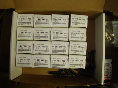
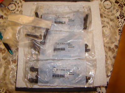
To figure out whether or not BMW changed the bearing clearances when they introduced the 702/703 bearings, it was going to require obtaining a full set of virgin 088/089 bearings and another set of virgin 702/703 bearings along with two sets of new connecting rod bolts. While I didn’t mind doing all the work, I couldn’t afford the $950 cost this would require. Thanks to many members of the m3post community, they donated the $950 to buy all new parts and make it possible to re-measure and re-confirm and/or refine the original findings.
Even though all of the original measurements are accurate and valid on their own merit (and will remain on record), they’re not made with virgin parts as if there were installed on the factory assembly line. To obtain these types of measurements would require measuring more than one virgin bearing of each 088/089 and 702/703 bearings on OEM connecting rods with brand new rod bolts. So I purchased and re-measured and entire new set of bearings and new connecting rod bolts. This will allow me to obtain as close to factory specifications as possible.
 Bearing Thickness Revisited
During the “redo” clearance measurements, I was also committed to using the best practice to obtain bearing materials thickness. Many of you following this thread recall the debates regarding the use and accuracy of ball-anvil micrometers versus test indicators to measure bearing thickness. In my last post on the topic, I demonstrated the effects of “cosine error” when using a test indicator to measure bearing thickness. Cosine error occurs when the test indicator is placed at an angle with respect to the measuring surface instead of the proper method of placing it 180-degrees with respect to the measuring surface. To compensate for cosine error, an adjustment factor is applied to the measurements to adjust them back to their original values as if the test indicator was used properly.
Just to settle this topic once and for all, I purchased a few more fixtures for the test indicator to help mathematically verify the cosine error. Then as one final test, I wanted to use the test indicator as it was designed to measure bearing thickness to see if I could get the ball-anvil micrometer and test indicator to agree without any cosine error correction.
Verifying “cosine error” with a test indicator
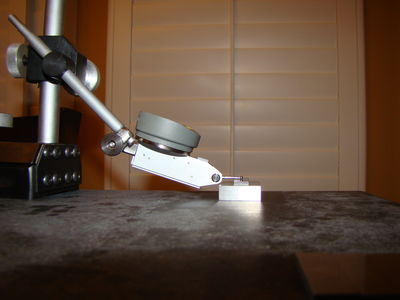
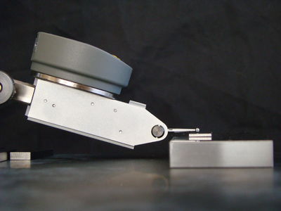
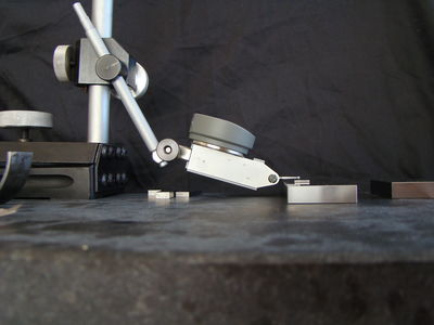
Before verifying the effects of cosine error on the test indicator, I first needed to verify the accuracy of the test indicator instrument on a flat surface. I set up the test indicator on a granite calibration block with the needle as perfectly parallel to the surface as I could obtain. Then using this technique, I verified the measurements of various calibration blocks.
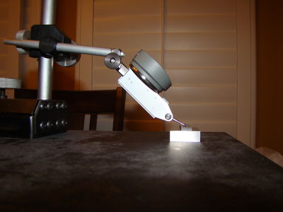
Following the initial flat-surface calibration (above), I changed the angle of the test indicator to 23-degrees. If such a cosine error exists, then the measurements of the test indicator will show significant changes.
Calibrated
Thickness | Measured
Thickness | Images | Measuremts
at 23-degrees | Cosine
Calculation | % Error | Images |
0.10000 | 0.10000 | | 0.10000 | 0.10000 | 0.00000 | |
0.10100 | 0.10100 | | 0.10015 | 0.10014 | 0.00853 | |
0.11000 | 0.11000 | | 0.11015 | 0.10934 | 0.00597 | |
0.12000 | 0.12005 | | 0.12135 | 0.11965 | 0.00331 | |
0.13000 | 0.13010 | | 0.13250 | 0.12992 | 0.00141 | |
The results clearly show the results of cosine error when using the test indicator in a non-standard position (180-degrees to the surface of measurement). Although not completely accurate, using the cosine error calculation, the results were adjusted back to their near-correct values. NOTE: There are some calculations missing from the tables above. The base measurement was 0.10000 inch above the flat surface. So adjustments were necessary to calculate this "translated" offset. These additional calculations are missing from the tables above and only apply to the % error values.
Re-measuring the bearing thicknesses on 702/703 bearings
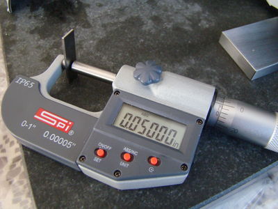
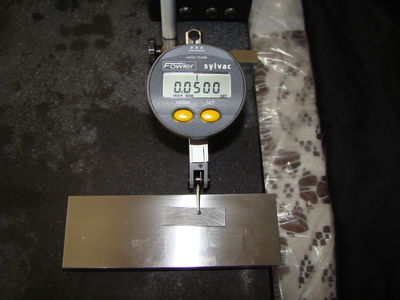
Now that we got the formalities out of the way of mathematically proving the cosine error of the test indicator, we can use the ball-anvil micrometer and test indicator to measure the same sets of bearings to see how closely they match. The electronic test indicator has a very nice "MIN" mode for these types of measurements. It is designed to capture the minimum thickness of an items such as a curved bearing surface. When programmed in this mode, once you place the bearing under the test indicator, you simply move the bearing back and forth a quarter inch or so while the test indicator measures and freezes the lowest ("MIN") point it finds. Using this technique, one can verify the measurements between the ball-anvil micrometer and test indicator.
Before I get started, I always calibrate the instruments. Then I take the measurements.
| 702 Bearings | 1 | 2 | 3 | 4 | 5 | 6 | 7 | 8 | Mode | Min. Dev. | Max. Dev. |
| Ball Anvil | 0.07850 | 0.07855 | 0.07850 | 0.07850 | 0.07855 | 0.07855 | 0.07850 | 0.07850 | 0.07850 | 0.00000 | 0.00005 |
| Test Indicator | 0.07850 | 0.07855 | 0.07845 | 0.07850 | 0.07855 | 0.07855 | 0.07855 | 0.07850 | 0.07855 | -0.00010 | 0.00000 |
| BA Photo | | | | | | | | | | | |
| TI Photo | | | | | | | | | | | |
| | | | | | | | | | | |
| 703 Bearings | 1 | 2 | 3 | 4 | 5 | 6 | 7 | 8 | Mode | Min. Dev. | Max. Dev. |
| Ball Anvil | 0.07865 | 0.07865 | 0.07870 | 0.07865 | 0.07865 | 0.07865 | 0.07865 | 0.07870 | 0.07865 | 0.00000 | 0.00005 |
| Test Indicator | 0.07870 | 0.07865 | 0.07870 | 0.07865 | 0.07865 | 0.07865 | 0.07865 | 0.07870 | 0.07865 | 0.00000 | 0.00005 |
| BA Photo | | | | | | | | | | | |
| TI Photo | | | | | | | | | | | |
| | | | | | | | | | | |
As these measurements show, whether using a ball-anvil micrometer, or properly used test indicator, the measurements will end up the same. I hope this settles this debate once and for all. For all future bearing thickness measurements, I will only use the ball-anvil micrometer.
Official 702/703 Bearing Thickness Measurements
| Engine | S65B40 | |
| Bearing Dimensions (702/703 Bearings) | Metric Dimensions | SAE (Inch) Dimensions |
| Nominal Bearing Thickness (Top, Blue) | 1.9977 mm | 0.07865 inch |
| Nominal Bearing Thickness (Bottom, Red) | 1.9939 mm | 0.07850 inch |
| Bearing Thickness Variance (Top, Blue) | 1.9977 - 1.9990 mm | 0.07865 - 0.07870 inch |
| Bearing Thickness Variance (Bottom, Red) | 1.9939 - 1.9952 mm | 0.07850 - 0.07855 inch |
| Bearing Tolerance (Top, Blue) | -0.0000, +0.0013 mm | -0.00000, +0.00005 inch |
| Bearing Tolerance (Bottom, Red) | -0.0000, +0.0013 mm | -0.00000, +0.00005 inch |
Re-measuring the bearing thicknesses on 088/089 bearings
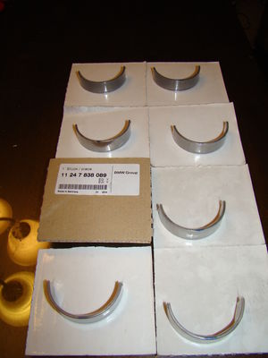
Since the 088/089 bearings are discontinued, the hardest part was to find the bearings in the first place. The BMW computers showed 70-pieces of 089 bearings in stock somewhere in the USA, but every time I placed the order, 703 bearings would show up instead. This same pattern repeated itself three times until my local BMW dealer was able to pull the right strings to purchase a full set of 089 bearings.
| 089 Bearings | 1 | 2 | 3 | 4 | 5 | 6 | 7 | 8 | Mode | Min. Dev. | Max. Dev. |
Ball Anvil | 0.07890 | 0.07885 | 0.07890 | 0.07885 | 0.07885 | 0.07885 | 0.07885 | 0.07880 | 0.07885 | -0.00005 | 0.00005 |
| BA Photo | | | | | | | | | | | |
In spite of my good fortune purchasing the 089 bearings, purchasing the 088's was not possible. I had BMWNA search the entire dealer network and distribution chains. There were zero 088's available. I then tried Canada, Mexico, South America, Germany, and Britain. I never got responses from Mexico or South America, but all the other responses came back negative. 088 bearings were no longer available.
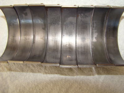
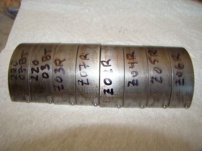
Since the upper bearings (089's) are the ones that take all the abuse, they are the ones most important to obtain. Thankfully, that's exactly what I was able to purchase. Obtaining virgin lower bearings was much less important because they seem to wear very little with respect to the tops. To obtain the best set of lower bearings I could for this test, I went through my collection of bearings and found the most pristine 088 bearings. I chose them with these criteria in mind: 1) low uniform wear across the shell; 2) Low-side variance shouldn't be greater than 089 bearings; 3) High-side variance should include as much range as possible to help simulate tolerance stack up. These are the bearings I selected from the collection.
| 088 Bearings | 1 | 2 | 3 | 4 | 5 | 6 | 7 | 8 | Mode | Min. Dev. | Max. Dev. |
| Ball Anvil | 0.07875 | 0.07880 | 0.07860 | 0.07860 | 0.07865 | 0.07865 | 0.07865 | 0.07865 | 0.07865 | -0.00005 | 0.00015 |
Official 088/089 Bearing Thickness Measurements
| Engine | S65B40 | |
| Bearing Dimensions (088/089 Bearings) | Metric Dimensions | SAE (Inch) Dimensions |
| Nominal Bearing Thickness (Top, Blue) | 2.0028 mm | 0.07885 inch |
| Nominal Bearing Thickness (Bottom, Red) | 1.9977 mm | 0.07865 inch |
| Bearing Thickness Variance (Top, Blue) | 2.0015 - 2.0041 mm | 0.07880 - 0.07890 inch |
| Bearing Thickness Variance (Bottom, Red) | 1.9964 - 2.0015 mm | 0.07860 - 0.07880 inch |
| Bearing Tolerance (Top, Blue) | -0.0013, +0.0013 mm | -0.00005, +0.00005 inch |
| Bearing Tolerance (Bottom, Red) | -0.0013, +0.0038 mm | -0.00005, +0.00015 inch |